Test and monitoring system for a sump pump installation having a self-monitoring liquid level sensing module

a technology monitoring system, which is applied in the direction of functional valve types, machines/engines, instruments, etc., can solve the problems of flooded basement, significant and often costly damage to items stored in the basement, and the inability to monitor the level of liquid level sensing module,

Active Publication Date: 2015-05-28
SCHWEITZER ENGINEERING LABORATORIES
View PDF6 Cites 28 Cited by
  • Summary
  • Abstract
  • Description
  • Claims
  • Application Information

AI Technical Summary

Problems solved by technology

Should the sump pump fail to operate for any reason, such as, for example, motor failure, pump failure, or power failure, and should the drain network continue to flow ground water into the sump pit, the pit will often eventually overflow from the top of the sump liner and flood into the basement.
This flooding may result in significant and often costly damage to items stored in the basement, as well as to existing basement improvements such as finished walls and furniture.
The drawback of these systems is that they only function when the pump is already in a condition in which it is no longer capable of preventing flooding, i.e. when the pump has failed and the pit is about to overflow.
This is frequently too late for corrective action to be taken.
Unfortunately, an alarm is only sounded at a time when operation of the pump is required to prevent flooding but the pump does not operate.
This, again, may be too late for any corrective action to be taken.
While the provision of these systems may reduce the likelihood of a system failure, they do not proactively identify a pump failure prior to an impending flood event requiring immediately operation of the pump.
In the event the test and monitoring system of the disclosure is utilized in a two pump installation, both pumps are independently tested and monitored, and a failure of either pump, or both pumps, results in an alarm being sounded and appropriate messages being sent to the owner and / or the owners' designee(s) by communications channels such as, for example, the Internet, cell phone data or land line telephone communication channels.
Prior monitoring systems are reactive in that they act only in the event the monitored sump installation is actually called on to evacuate rising ground water, which may be only after extended periods of non-operation.

Method used


Image

  • Test and monitoring system for a sump pump installation having a self-monitoring liquid level sensing module
  • Test and monitoring system for a sump pump installation having a self-monitoring liquid level sensing module
  • Test and monitoring system for a sump pump installation having a self-monitoring liquid level sensing module

Examples


Embodiment Construction

[0059]The following description of the preferred embodiments is merely exemplary in nature and is no way intended to limit the disclosure, its application or use.

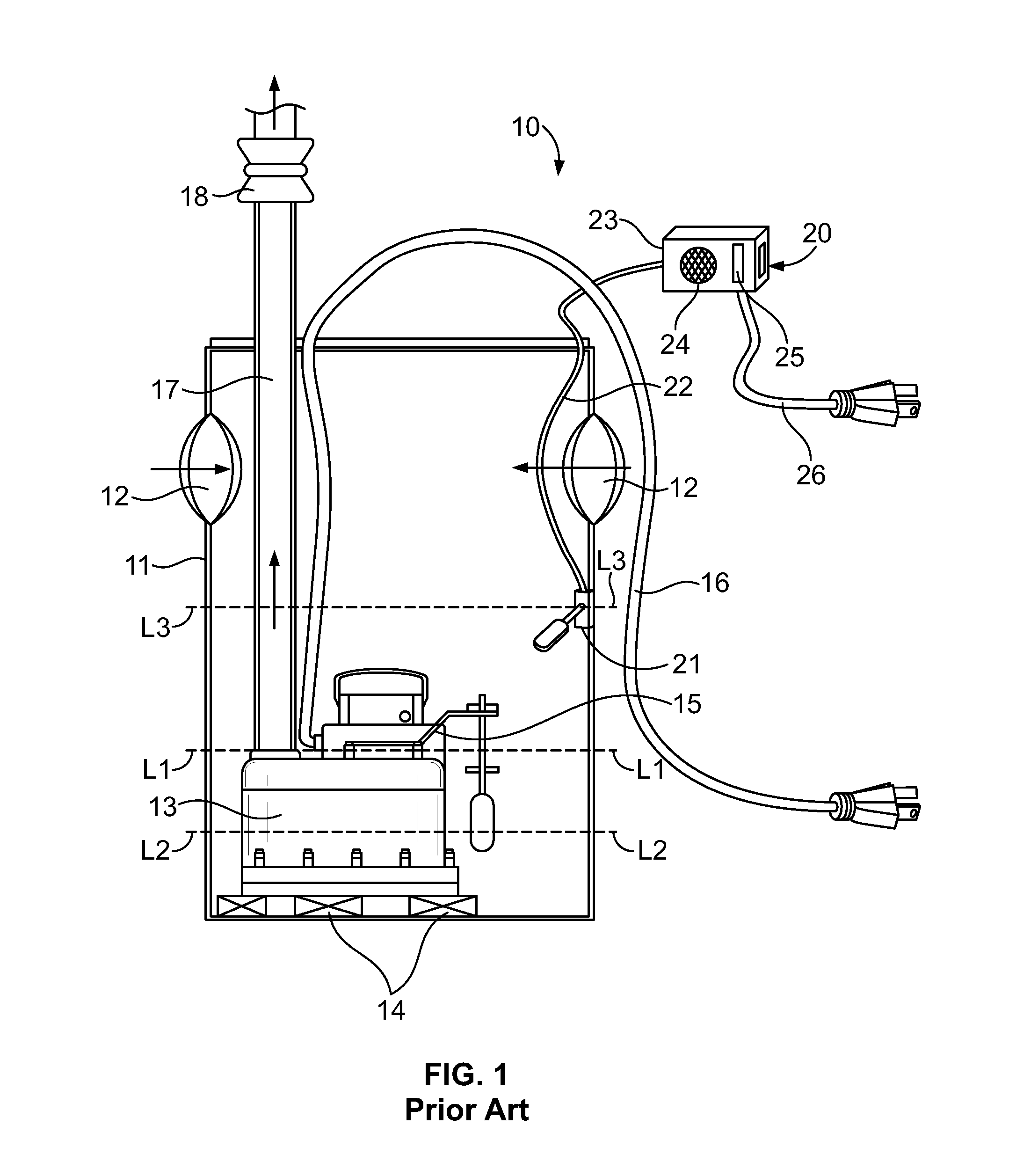
[0060]Referring to FIG. 1, a prior art sump pump installation 10 of the type commonly used in basements of homes or businesses generally consists of a sump container or liner 11 having multiple inlets 12 through which drain water is received from one or more perforated hose or tile systems (not shown) disposed around the foundation footings of the building in which the sump pump installation is located. A motor driven sump pump 13 is typically positioned at or near the bottom of container 11, and may be supported by one or more bricks 14 or other spacers located between sump pump 13 and the bottom of container 11. Sump pump 13 may include an integral float switch assembly 15 which forms part of an electric circuit including a power cord 16 which supplies electric power to the pump motor upon the water level in container 11 ...


PUM


Abstract

A liquid level sensing module for sensing a high liquid level in a sump container rising comprises a first liquid-actuated switch which provides a first output signal upon the liquid level reaching a first level, and a second liquid-actuated switch which provides a second output signal upon the liquid level reaching a second level above the first. A delay circuit delays the first output signal by a period if time sufficient for the liquid to rise from the first switch level to the second switch level to produce a delayed output signal. An alarm circuit produces a fault signal indicating a switch module fault upon the occurrence of the second output signal. An alarm circuit produces a fault signal upon the occurrence of the second output signal in the absence of the first output signal, or upon the occurrence of the delayed output signal in the absence of the second output signal, and the occurrence of either the delayed output signal or the second output signal, producing an alarm signal indicative of the pump failing to function.

Description

CROSS-REFERENCE TO RELATED APPLICATIONS[0001]This continuation-in-part application claims the benefit of U.S. Provisional Patent Application No. 61 / 908,881 filed on Nov. 26, 2013, U.S. Design patent application No. 29 / 486,504, filed on Mar. 31, 2014, and U.S. Non-Provisional patent application Ser. No. 14 / 281,525 filed on May 19, 2014, and further incorporates by reference in their entireties the following seven contemporaneously filed applications: (1) application attorney docket number 0222-0006.03, entitled “Test And Monitoring System For A Dual Stamp Pump Installation” (2) application attorney docket number 0222-0006.04, entitled “Test And Monitoring System For A Battery-Powered DC Sump Pump Installation;” (3) application attorney docket number 0222-0006.05, entitled “Test And Monitoring System For A Sump Pump Installation Having A Self-Monitoring Valve Module For Admitting Water To The Sump Pit;” (4) application attorney docket number 0222-0006.07, entitled “Test And Monitoring...

Claims


Application Information

Patent Timeline
Patent Type & Authority Applications(United States)
IPC IPC(8): G01F23/62
CPCG01F23/62G01F23/74F04D13/086F04D15/0005F04D15/0088F04D15/0227F16K21/18G01F23/603H01H35/18H01H47/00
Inventor CUMMINGS, EUGENE M.
Owner SCHWEITZER ENGINEERING LABORATORIES
Why Eureka
Try Eureka