
Heat radiation sheet and method of manufacturing same

Inactive Publication Date: 2015-05-28
AMOGREENTECH CO LTD
View PDF7 Cites 2 Cited by
  • Summary
  • Abstract
  • Description
  • Claims
  • Application Information

AI Technical Summary

Benefits of technology

The present invention provides a heat radiation sheet that is formed using an electrospinning method to enhance its blanking performance. The adhesive layer of the sheet contains a heat conductive material to improve its heat radiation performance.

Problems solved by technology

Typically, electronic equipment such as computers, portable personal terminals, or communicator devices has a serious concern for a residual image problem and an intrinsic system stability when excessive thermal energy generated from the inside of the electronic equipment was not be diffused to the outside thereof.
This thermal energy may reduce the lifetime of the electronic equipment, or cause failure and malfunction of the electronic equipment, and in severe cases, may provide a cause of explosion or fire.
However, since the conventional heat radiation sheet uses an adhesive foam sheet attached on a surface of a metal plate, the conventional heat radiation sheet becomes thick, to thus cause a problem of making it difficult to use the conventional heat radiation sheet in thin electronic equipment such as portable electronic equipment.
However, since a foam sheet has adhesiveness, it is difficult to blank the heat radiation sheet precisely during blanking the conventional heat radiation sheet.

Method used


Image

  • Heat radiation sheet and method of manufacturing same
  • Heat radiation sheet and method of manufacturing same
  • Heat radiation sheet and method of manufacturing same

Examples


first embodiment

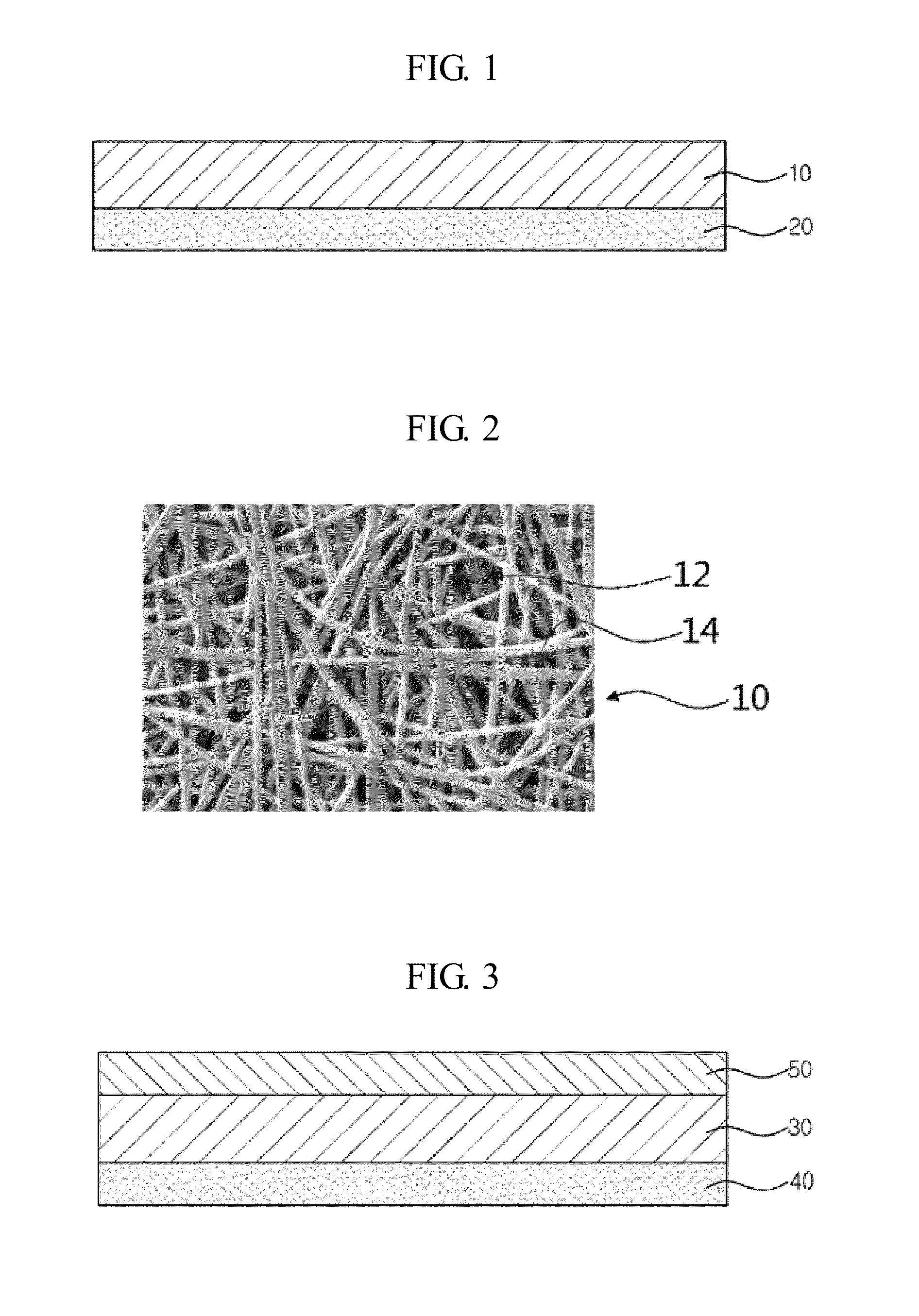
[0022]Referring to FIGS. 1 and 2, the heat radiation sheet includes: a heat radiation layer 10 that is formed in a nano-web by an electrospinning method in which a heat conductive material is contained in the heat radiation layer 10, to thus have thermal conductivity; and an adhesive layer 20 that is laminated on one surface or both surfaces of the heat radiation layer 10.

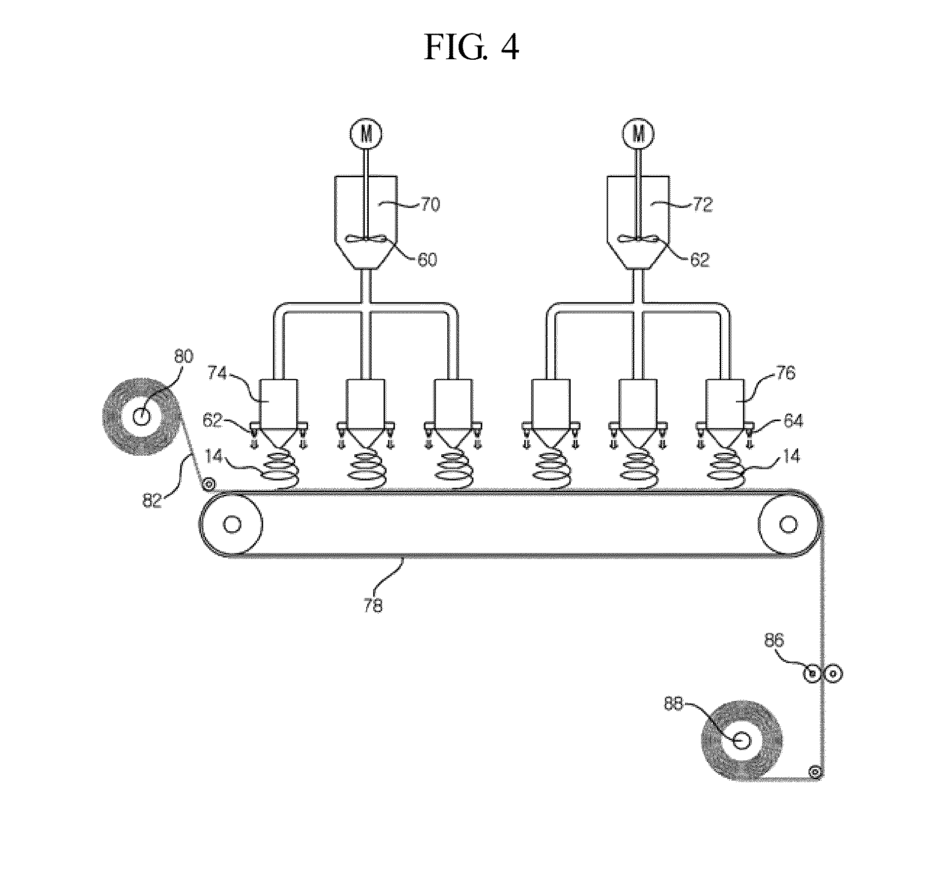
[0023]The heat radiation layer 10 is formed by the following steps of: mixing a polymer material that can be electrospun and a solvent, or the polymer material, a heat conductive material, and the solvent at a constant mixture rate, to thus produce a spinning solution; electrospinning the spinning solution to thus form nanofibers 14; and accumulating the nanofibers 14 to thus form a nano-web having a plurality of pores 12. Here, the term “nano-web” can be called the ‘web’ shortly.

[0024]Here, the spinning method that is applied to the present invention can employ any one selected from general electrospinning, air-e...

second embodiment

[0041]FIG. 3 is a cross-sectional view of a heat radiation sheet according to the present invention.

[0042]Referring to FIG. 3, the heat radiation sheet according to the second embodiment includes a substrate 30 that is formed in a nano-web shape by the electrospinning method, an adhesive layer 40 that is laminated on one surface of the substrate 30, and a metal layer 50 that is coated on the other surface of the substrate 30 and having thermal conductivity.

[0043]The substrate 30 is formed by the following steps of: mixing a polymer material and a solvent at a constant rate to thus produce a spinning solution having a viscosity so as to be electrospun; electrospinning the spinning solution to thus form nanofibers; and accumulating the nanofibers to thereby form the substrate 30 having a number of pores in a nano-web form.

[0044]Further, the substrate 30 may be formed in the same structure as the heat radiation layer 10 according to the first embodiment. That is, the substrate 30 may b...


PUM

PropertyMeasurementUnit
Electrical conductoraaaaaaaaaa
Thermal conductivityaaaaaaaaaa

Abstract

A heat radiation sheet including: a heat radiation layer that is formed in the form of a nano-web having a plurality of pores by electrospinning a spinning solution that is obtained by mixing a polymer material and a solvent, or the polymer material, a heat conductive material, and the solvent; and an adhesive layer that is laminated on one surface or both surfaces of the heat radiation layer, and that is formed in the form of the nano-web by electrospinning an adhesive material that is obtained by an adhesive, the heat conductive material, and the solvent.

Description

CROSS REFERENCE TO RELATED APPLICATIONS[0001]This application is a divisional of International Application No. PCT / KR2013 / 006838, filed on Jul. 30, 2013, which claims priority to and the benefit of Korean Application Nos. 10-2012-0085769, filed on Aug. 6, 2012 and 10-2013-0089635, filed on Jul. 29, 2013 in the Korean Patent Office, the entire contents of which are incorporated herein by reference.TECHNICAL FIELD[0002]The present invention relates to a heat radiation sheet that is mounted in an electronic device, to thereby radiate heat generated from the inside of the electronic device to the outside of the electronic device, and more particularly, to a heat radiation sheet that is made in the form of a nano-web form by way of an electrospinning method, and a method of manufacturing same.BACKGROUND ART[0003]Typically, electronic equipment such as computers, portable personal terminals, or communicator devices has a serious concern for a residual image problem and an intrinsic system...

Claims


Application Information

Patent Timeline
IPC IPC(8): F28F21/02F28F21/06F28F21/08D01D5/00
CPCF28F21/02F28F21/089F28F21/065D01D5/0007B32B5/24B32B7/12B32B27/06B32B27/12B32B37/02D01D5/003D01F1/10H01L23/3733F28F2255/06H01L23/3737H01L2924/0002H01L2924/00D04H1/728D04H1/413D04H1/4374D06M11/83
Inventor LEE, SEUNG HOONJUNG, YONG SIKSO, YUN MI
Owner AMOGREENTECH CO LTD
Learn More