Light emitting device
- Summary
- Abstract
- Description
- Claims
- Application Information
AI Technical Summary
Benefits of technology
Problems solved by technology
Method used
Image
Examples
first embodiment
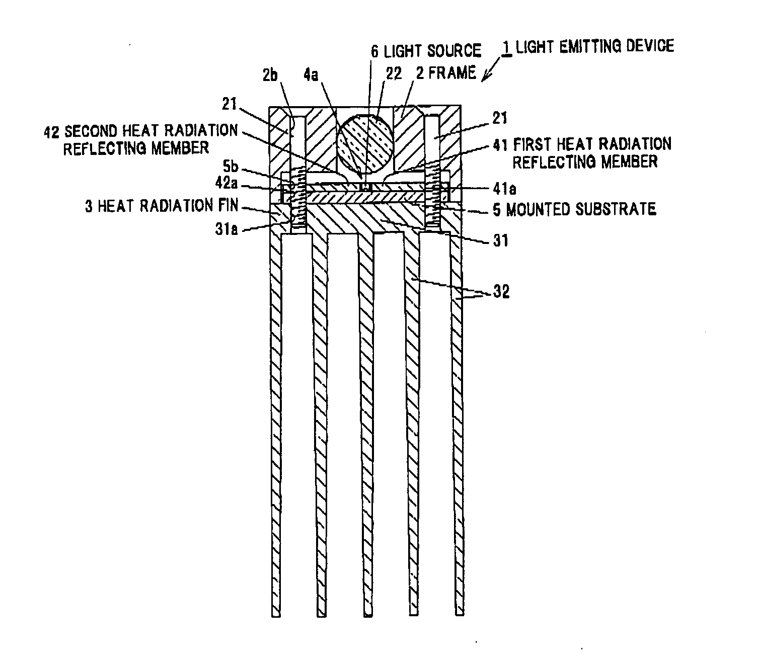
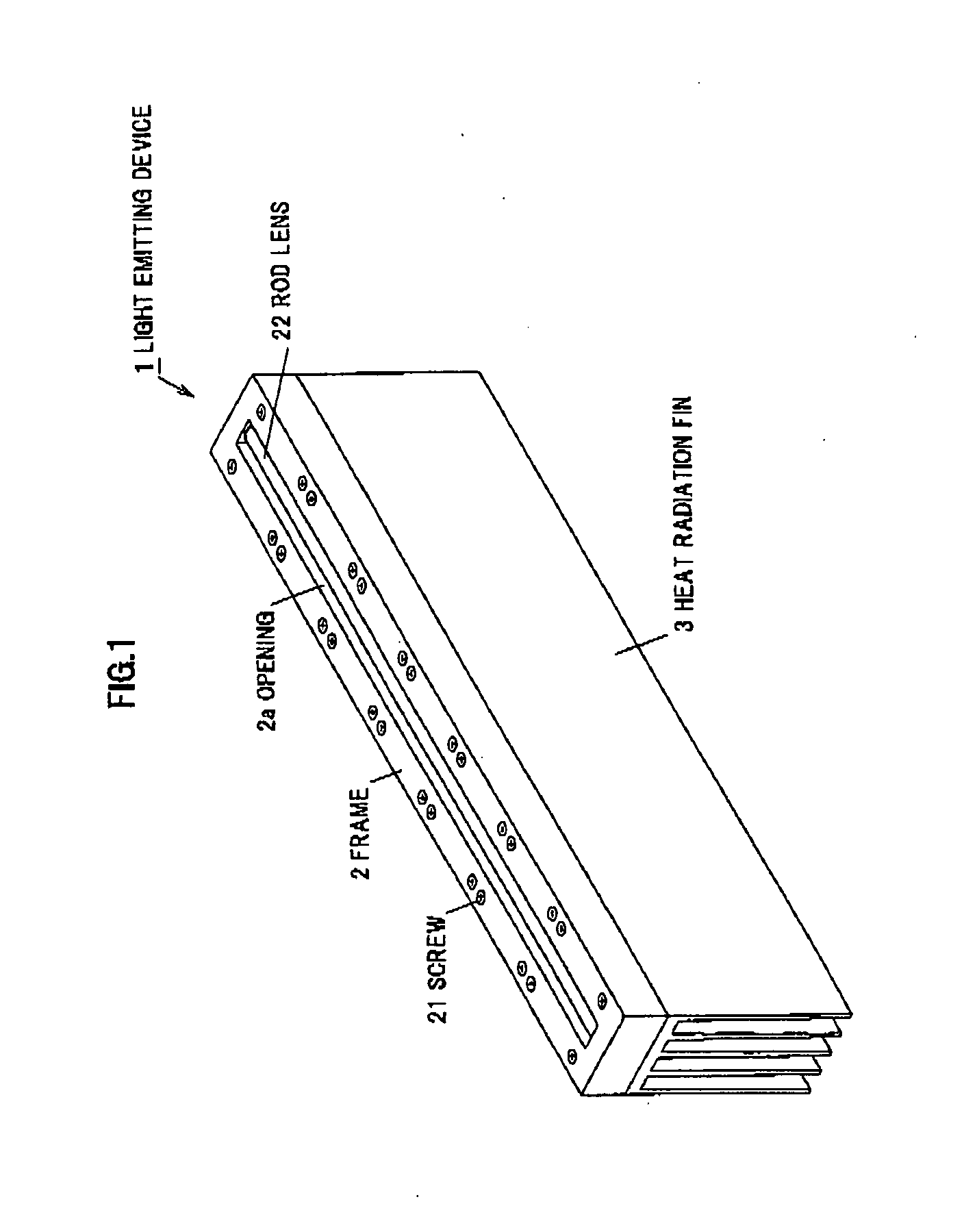
[0052]FIG. 1 is a perspective view schematically showing a light emitting device according to a first embodiment of the invention. A light emitting device 1 is used for, for example, lighting of an inspection device for detecting a scratch or a stain of a liquid crystal film.
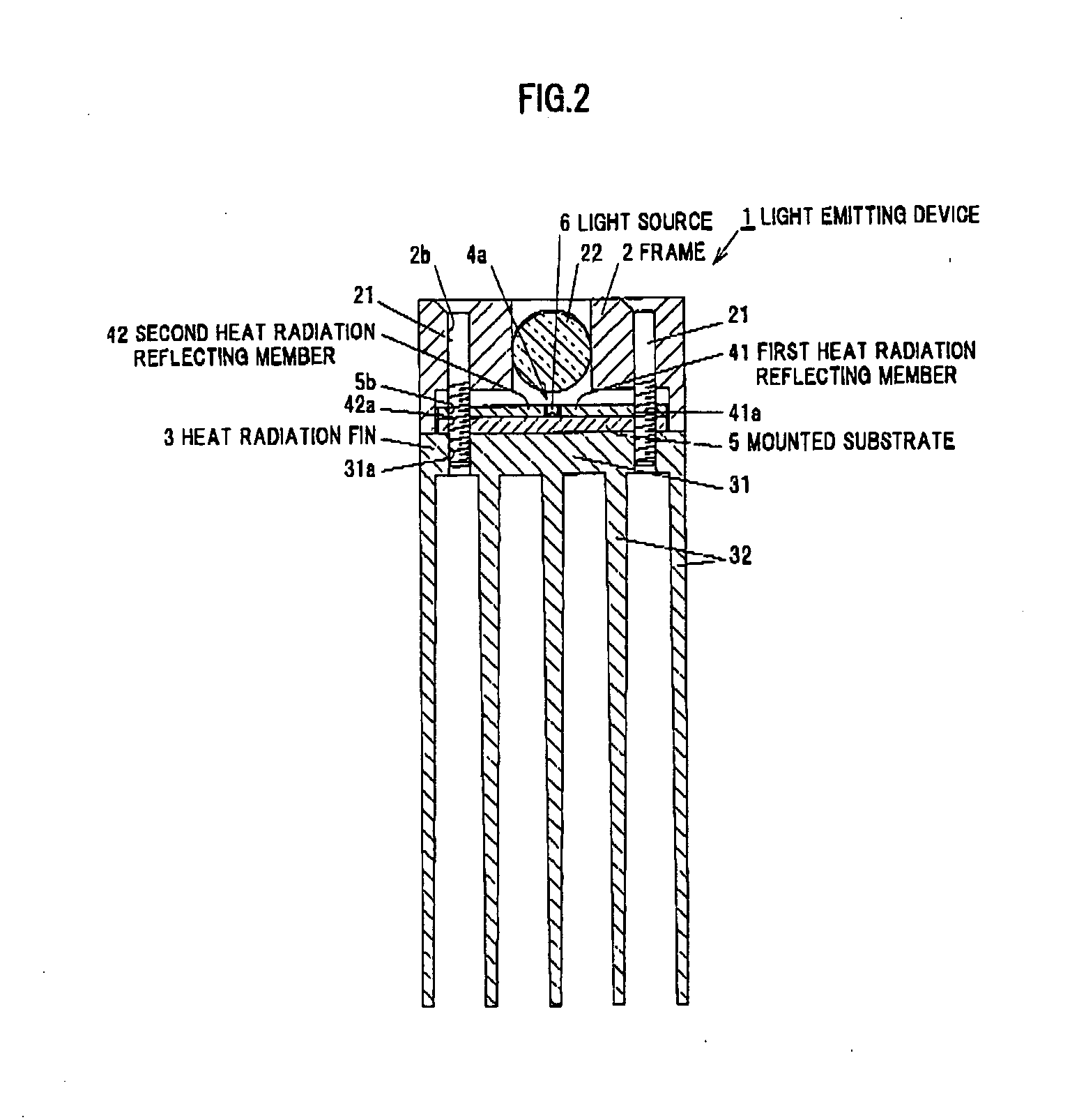
[0053]The light emitting device 1 includes a frame 2 having an opening 2a of an linear shape and a heat radiation fin 3 fastened to the frame 2 by screws 21. The light emitting device 1 has almost a rectangular parallelepiped shape as a whole, and hereinafter it will be explained about a case that the frame 2 is located at upper position and the heat radiation fin 3 is located at the lower position. The opening 2a is formed on the upper surface of the frame 2 to have a linear shape, and a rod lens 22 is disposed within the opening 2a.
[0054]FIG. 2 is a cross-sectional view schematically showing the light emitting device 1. Between the frame 2 and the heat radiation fin 3, the light emitting device 1 includes a m...
second embodiment
[0117]Next, a second embodiment of the invention will be explained referring to FIGS. 11 to 13.
[0118]In the first embodiment and the modification thereof, a case that a radiation and reflection member is adopted, the member being configured so as to guide a light of the light source 6 in a predetermined direction due to the reflection by the reflecting surface and to carry out radiation, has been explained, but in the light emitting device 1 according to the embodiment, a light guiding plate as an optical member is used, the light guiding plate allowing a light of the light source 6 to enter into a translucent material, guiding the incident light in a predetermined direction by an internal reflection, and simultaneously carrying out radiation. The light emitting device is used for, for example, a lighting device with which a backlight of a liquid crystal display device or a fluorescent bulb is replaced.
[0119]FIG. 11A is a plan view schematically showing a light emitting device accor...
modification 1
of the Second Embodiment
[0154]The above-mentioned second embodiment can be modified as explained below. Namely, the light emitting device 10 according to the second embodiment has a configuration that a pair of the first and second light guiding plates 71, 72 are included and a plurality of the light sources 6 are disposed in a linear shape between the pair of the first and second light guiding plates 71, 72, a light emitting device having a configuration that a single light guiding plate is included and a plurality of the light sources 6 are disposed in concave portions formed on the peripheral part thereof can be also adopted.
[0155]FIG. 14A is a plan view schematically showing a light emitting device 11 according to a first modification of the second embodiment, FIG. 14B is a cross-sectional view taken along the line E-E in FIG. 14A. FIG. 14C is a partially enlarged plan view of “F” part shown in FIG. 14A.
[0156]The light emitting device 11 includes a case 91, a single light guidin...
PUM
 Abstract
Description
Claims
Application Information
 - R&D
- Intellectual Property
- Life Sciences
- Materials
- Tech Scout
- Unparalleled Data Quality
- Higher Quality Content
- 60% Fewer Hallucinations
Browse by: Latest US Patents, China's latest patents, Technical Efficacy Thesaurus, Application Domain, Technology Topic, Popular Technical Reports.
© 2025 PatSnap. All rights reserved.Legal|Privacy policy|Modern Slavery Act Transparency Statement|Sitemap|About US| Contact US: help@patsnap.com


