AI technical title is built by Patsnap AI team. It summarizes the technical point description of the patent document.
a technology of subterranean formation and apparatus, which is applied in the direction of drinking water installation, borehole/well accessories, construction, etc., can solve the problems of undesirable substances, affecting the porosity and permeability of the formation near the wellbore, and forming to yield, so as to reduce, or minimise, the change in porosity and/or permeability
Active Publication Date: 2015-05-28
HALLIBURTON MFG & SERVICES
View PDF4 Cites 7 Cited by
Summary
Abstract
Description
Claims
Application Information
AI Technical Summary
This helps you quickly interpret patents by identifying the three key elements:
Problems solved by technology
Method used
Benefits of technology
Benefits of technology
The patent describes a method of increasing the porosity and permeability of the formation surrounding a wellbore by using either exertive force or drawdown pressure, or a combination of both. The method can be used to modify the porosity and permeability of the formation from an initial or current level, or after depletion from the reservoir. By maintaining or reducing the porosity and permeability of the formation during production, the method can improve the efficiency of the wellbore.
Problems solved by technology
Such modification or redistribution of these forces can, in some cases, cause the formation to yield.
Furthermore, the porosity and permeability of the formation near the wellbore is affected.
When producing from a well, other substances can be produced which are undesirable.
This production of water can be commercially unhelpful.
For example, these factors can also increase the level of effort or costs associated with maintaining the well in production, or at least maintaining the well in production at a commercially beneficial level.
Method used
Image
Click on the blue label to locate the original text in one second.
Reading with bidirectional positioning of images and text.
Examples
Embodiment Construction
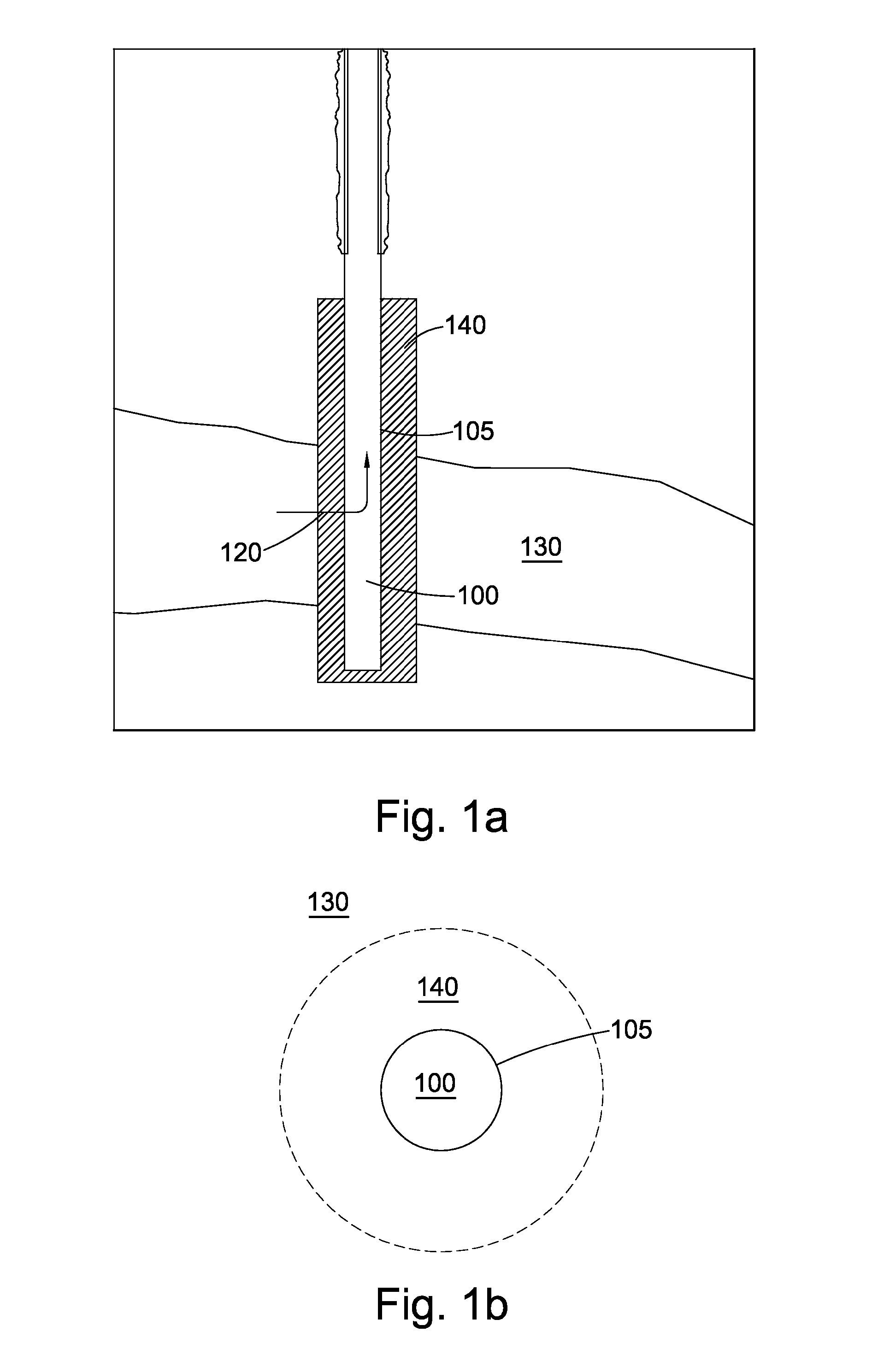
[0099]FIG. 1a shows a simplified section of a wellbore 100 that has been drilled into or through rock formation having a reservoir 130. For the following description, reference is made to a hydrocarbon reservoir (e.g., an oil and / or gas field). However, the reservoir 130 may equally be subterranean water reservoir (e.g., potable water), or the like. FIG. 1b shows a plan section of the wellbore of FIG. 1a. By way of an example only, the following embodiments have be described in relation to producing from the reservoir 130, in other words, producing fluid, and in particular oil 120, from the reservoir 130 to the surface (not shown) by known methods. However, further embodiments include injecting fluid into the reservoir 130 from the wellbore 100 (e.g., injecting water to assist with production, and / or hydraulic fracturing fluid, etc.). Given the detailed description below, a skilled person will readily be able to implement those further embodiments.
[0100]The wellbore 100 is essential...
PUM
Abstract
A method is for use with subterranean formations, such as oil and / or gas reservoirs. In some examples (e.g., production examples), the method improves the production from that formation. Some of the examples of the method describe selecting both an exertive force (e.g., a pressure) to apply at a wellbore, but together with a drawdown pressure at the wellbore to modify operations (e.g., improve production) at that subterranean formation. The selection of one or both of the exertive force and drawdown pressure may be based on the downhole environment at that wellbore, which can include the porosity and / or permeability of a near-wellbore formation radially surrounding a wellbore. The exertive force and drawdown pressure may be specifically selected to modify the porosity and / or permeability of the near-wellbore formation.
Description
REFERENCE TO RELATED APPLICATION[0001]This application is a United States National Phase application of PCT Application No. PCT / GB2013 / 051558 filed on Jun. 14, 2013, which claims priority to United Kingdom Application No. 1210532.6 filed on Jun. 14, 2012.TECHNICAL FIELD[0002]The invention relates to the field of subterranean formation methods and apparatus, such as production methods, injection methods, etc., as well as associated apparatus.BACKGROUND OF THE INVENTION[0003]When a well is provided into a subterranean formation, such as a reservoir, the step of drilling the wellbore and removal of, for example, oil from the reservoir causes the forces, including stresses, and pressures, in the formation surrounding the wellbore to be modified, or redistributed. The modification, or redistribution, of forces, including stresses, pressures, etc., of the formation surrounding the wellbore may occur when producing from a well, for example when extracting oil and / or gas, as well as when in...
Claims
Application Information
Patent Timeline
Application Date:The date an application was filed.
Publication Date:The date a patent or application was officially published.
First Publication Date:The earliest publication date of a patent with the same application number.
Issue Date:Publication date of the patent grant document.
PCT Entry Date:The Entry date of PCT National Phase.
Estimated Expiry Date:The statutory expiry date of a patent right according to the Patent Law, and it is the longest term of protection that the patent right can achieve without the termination of the patent right due to other reasons(Term extension factor has been taken into account ).
Invalid Date:Actual expiry date is based on effective date or publication date of legal transaction data of invalid patent.
Patent Type & AuthorityApplications(United States)

