
Boom extending and retracting apparatus of a crane

a technology of extending and retracting equipment and cranes, which is applied in the direction of safety gear, load-engaging elements, lifting devices, etc., can solve the problems of increasing the burden on the operator, taking time to extend or retract the telescopic boom,

Active Publication Date: 2015-05-28
TADANO LTD
View PDF0 Cites 6 Cited by
  • Summary
  • Abstract
  • Description
  • Claims
  • Application Information

AI Technical Summary

Benefits of technology

The present invention relates to a boom extending and retracting apparatus for cranes, which allows for the optional use of a differential fluid circuit or a normal fluid circuit for extending the telescopic boom. The control part can switch between the two modes by repeatedly operating the operating lever in the extension side, making the activating mode of the fluid circuit easier to switch and more convenient for the operator. The invention aims to reduce the burden on the operator and improve the convenience of the telescopic boom, while also reducing the cost and space requirement for the switch.

Problems solved by technology

However, when the plurality of boom members are slid one by one with one telescopic cylinder, it may take time to extend or retract the telescopic boom.
Therefore, management items during the work are increased, and consequently the burden on the operator increases.

Method used


Image

  • Boom extending and retracting apparatus of a crane
  • Boom extending and retracting apparatus of a crane
  • Boom extending and retracting apparatus of a crane

Examples


embodiment 1

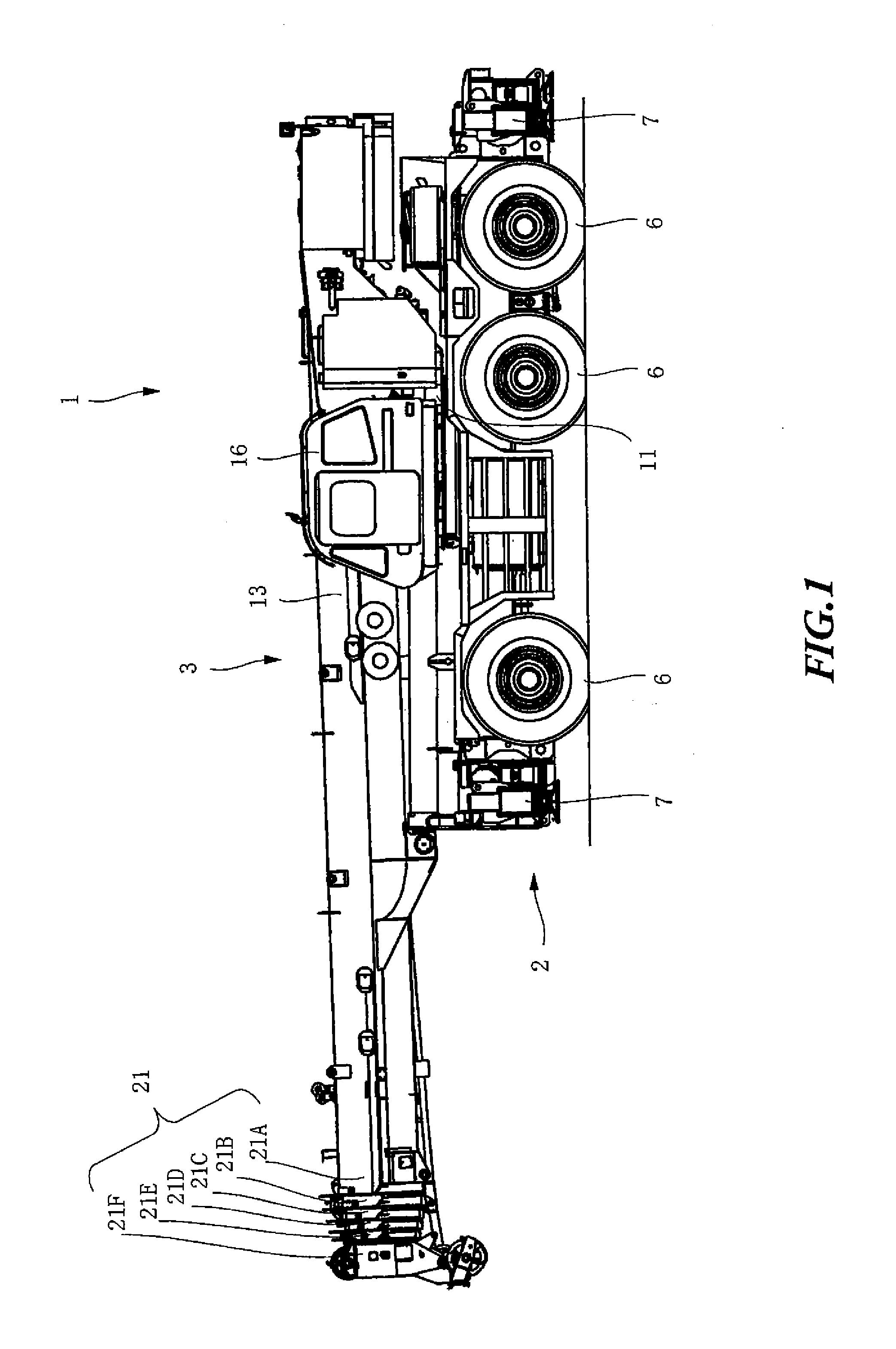
[0026]FIG. 1 is a side view of a mobile crane 1 which is equipped with a boom extending and retracting apparatus according to Embodiment 1 of the present invention. The mobile crane 1 in FIG. 1 includes a vehicle 2 and a crane apparatus 3. The vehicle 2 has wheels 6 and runs by an engine (not shown) as a power source. In addition, the vehicle 2 has outriggers 5 that can extend outwardly in the right-to-left direction from the sides of the vehicle 2. Each of the outriggers 7 has a hydraulic jack cylinder, and contacts with the ground when the jack cylinder is extended downwardly. When the outriggers 7 are extended outwardly in the right-to-left direction and contact with the ground there, the vehicle 2 is stabilized. As a result, it is possible to widen the operation range of the crane 1.

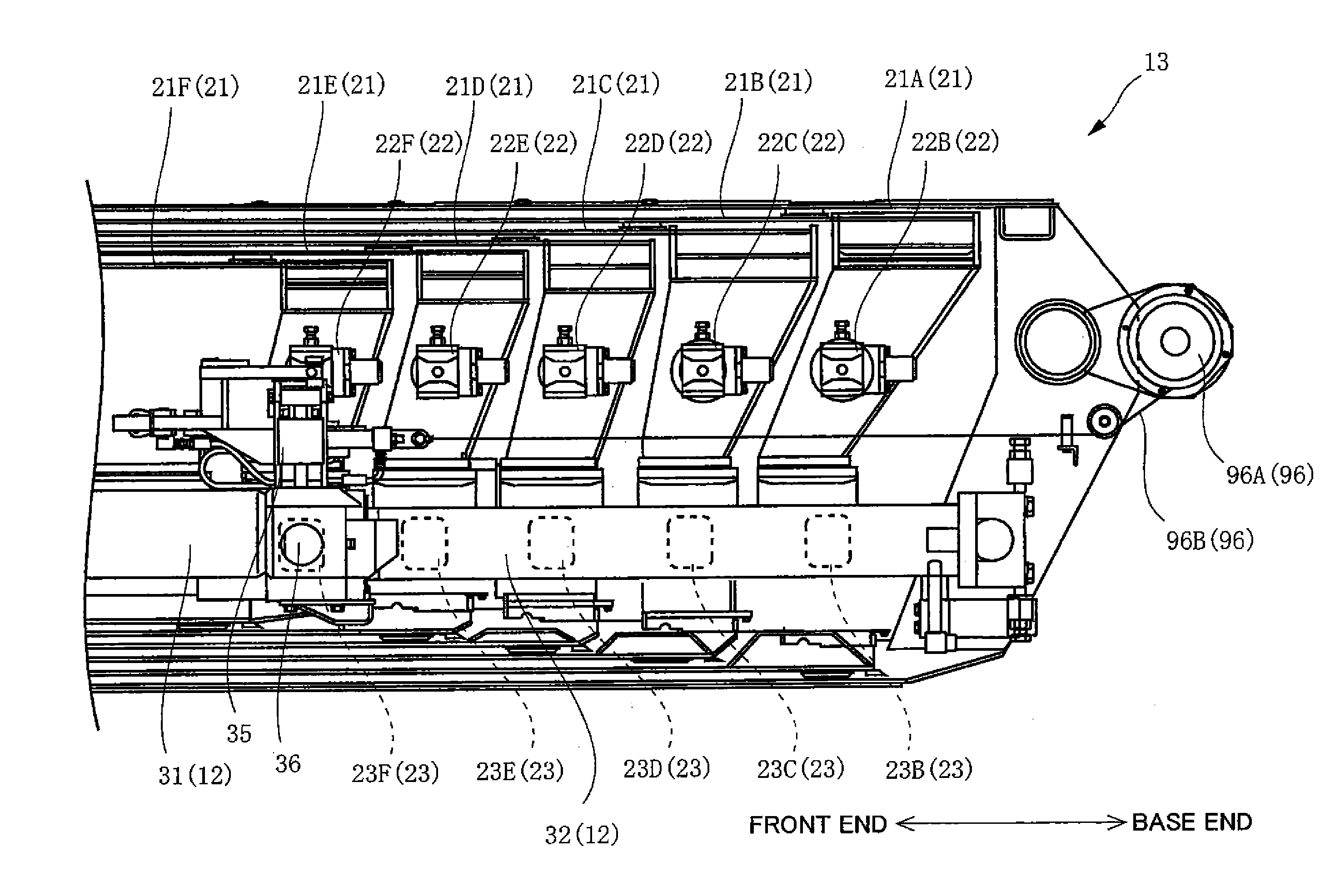
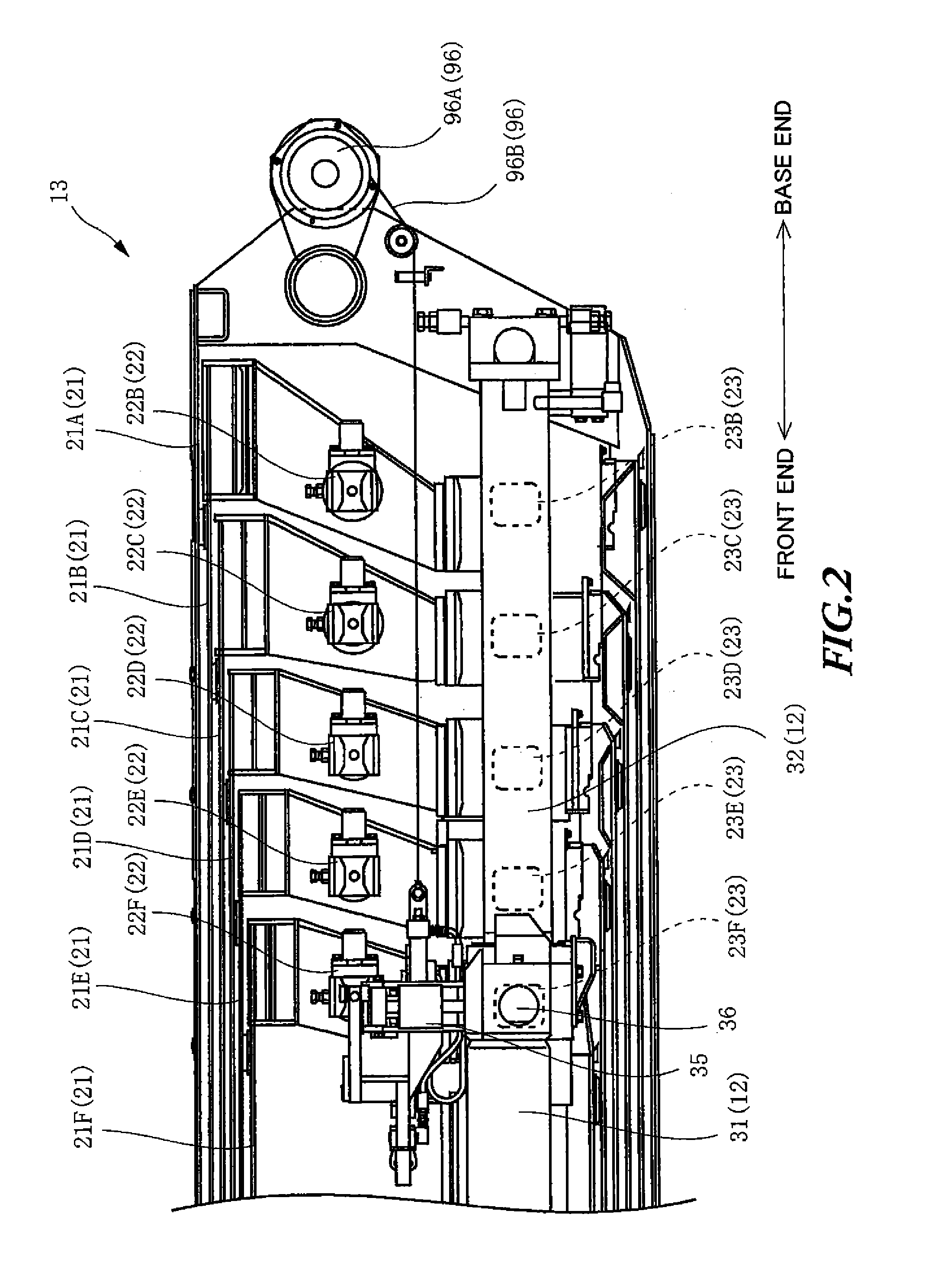
[0027]The crane apparatus 3 includes a swivel base 11, a telescopic boom 13 incorporating a telescopic cylinder 12 in FIG. 2, a hydraulic circuit 14 in FIG. 3, a hydraulic control system 15 in FIG. 3...

embodiment 2

[0072]Next, the boom extending and retracting apparatus according to Embodiment 2 will be described. The basic configurations and the actions of the mobile crane 1 and the boom extending and retracting apparatus are the same as in Embodiment 1, and therefore the same reference numerals are assigned and overlapping description will be omitted. Hereinafter, the difference from Embodiment 1 will be mainly described.

[0073]FIG. 7 is a drawing explaining the hydraulic circuit 14 and the hydraulic control system 15 of the boom extending and retracting apparatus according to Embodiment 2 of the present invention. The hydraulic circuit 14 is the same as in Embodiment 1.

[0074]The operating part 91 of the hydraulic control system 15 has a differential changeover switch 111 to select and to set the usage of the differential hydraulic circuit mode. The differential changeover switch 111 can selects between the using mode of the differential hydraulic circuit and the un-using mode of the differen...


PUM


Abstract

There is provided a boom extending and retracting apparatus that can improve the convenience of the telescopic boom while reducing the burden on the operator. The boom extending and retracting apparatus of the crane chooses the mode of the fluid circuit between the normal fluid circuit and the differential fluid circuit to slide a plurality of boom members by one telescopic cylinder. After the operating lever is turned to an extension side and the controller starts extending the telescopic boom using the differential fluid circuit, when the operating lever is turned to the extension side again via the neutral position, the controller chooses the normal fluid circuit to extend the telescopic boom using the normal fluid circuit.

Description

CROSS-REFERENCES TO RELATED APPLICATIONS[0001]This application claims the benefit of Japanese Patent Application No. 2013-243984, filed Nov. 26, 2013, which is incorporated herein by reference.BACKGROUND[0002]1. Technical Field[0003]The present invention relates to a boom extending and retracting apparatus that extends and retracts a telescopic boom of a crane.[0004]2. Related Art[0005]A crane is equipped with a telescopic boom to lift goods. There has been known a telescopic boom in which a plurality of boom members are provided as to be slid with respect to each other and one telescopic cylinder is provided to slide the plurality of boom members one by one to extend. However, when the plurality of boom members are slid one by one with one telescopic cylinder, it may take time to extend or retract the telescopic boom. Therefore, in a crane disclosed in Patent Literature 1, a differential fluid circuit as well as a normal fluid circuit is provided for a fluid circuit to inject fluid...

Claims


Application Information

Patent Timeline
Patent Type & Authority Applications(United States)
IPC IPC(8): B66C23/70
CPCB66C23/705B66F9/22
Inventor MATSUMOTO, NAOYUKI
Owner TADANO LTD
Learn More