
Thermally Enhanced Package with Lid Heat Spreader

a technology of heat spreader and package, which is applied in the direction of semiconductor devices, electrical equipment, semiconductor/solid-state device details, etc., can solve the problems of packaging reliability challenges, significant challenges in the design and packaging of these devices, and the inefficiency of the use of individual lids in the manufacture of multiple integrated circuits

Active Publication Date: 2015-05-28
NXP USA INC
View PDF7 Cites 14 Cited by
  • Summary
  • Abstract
  • Description
  • Claims
  • Application Information

AI Technical Summary

Benefits of technology

The present invention relates to an improved integrated circuit chip package and manufacture method that addresses various problems in the art. The invention provides an exposed lid heat spreader that improves thermal transfer and reliability, while also reducing the size of the package and the number of individual heat spreaders required. The invention uses a heat spreader array that is attached to a layer of molding tape for placement on a heated bottom plate of a compression mold system. The heat spreader array structure is formed by applying a stamp or selective etch process to define a heat spreader array with recesses and peripheral lid links or expanded pedestal recess areas. The invention addresses the need for an improved integrated circuit chip package with efficient heat spreading and reliable packaging.

Problems solved by technology

As the density and complexity of integrated circuit devices increases and the size of such devices shrinks, significant challenges are posed in the design and packaging of these devices.
One challenge is to provide a thermal path within the package to conduct heat away from the integrated circuit die, where conventional approaches for removing heat generated within the package typically use individual metal lids or heat spreaders that are separately applied to individual packaged units and then encapsulated with molding compound.
The use of individual lids is not efficient for the manufacture of multiple integrated circuits in terms of the separate application requirements for separate heat spreaders and also in forcing the use of a larger body size to allow room beyond the edge of the lid for saw singulation.
Such conventional approaches also present packaging reliability challenges caused by overheating resulting from poor thermal transfer from the integrated circuit die.

Method used


Image

  • Thermally Enhanced Package with Lid Heat Spreader
  • Thermally Enhanced Package with Lid Heat Spreader
  • Thermally Enhanced Package with Lid Heat Spreader

Examples


Embodiment Construction

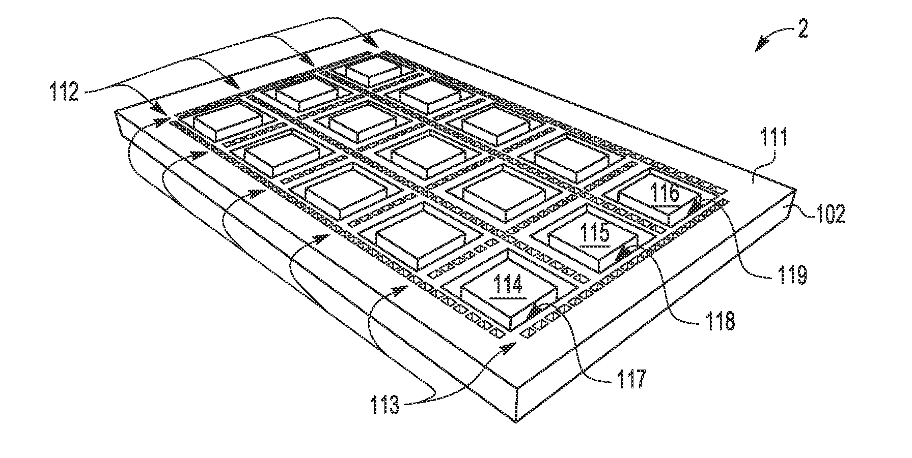
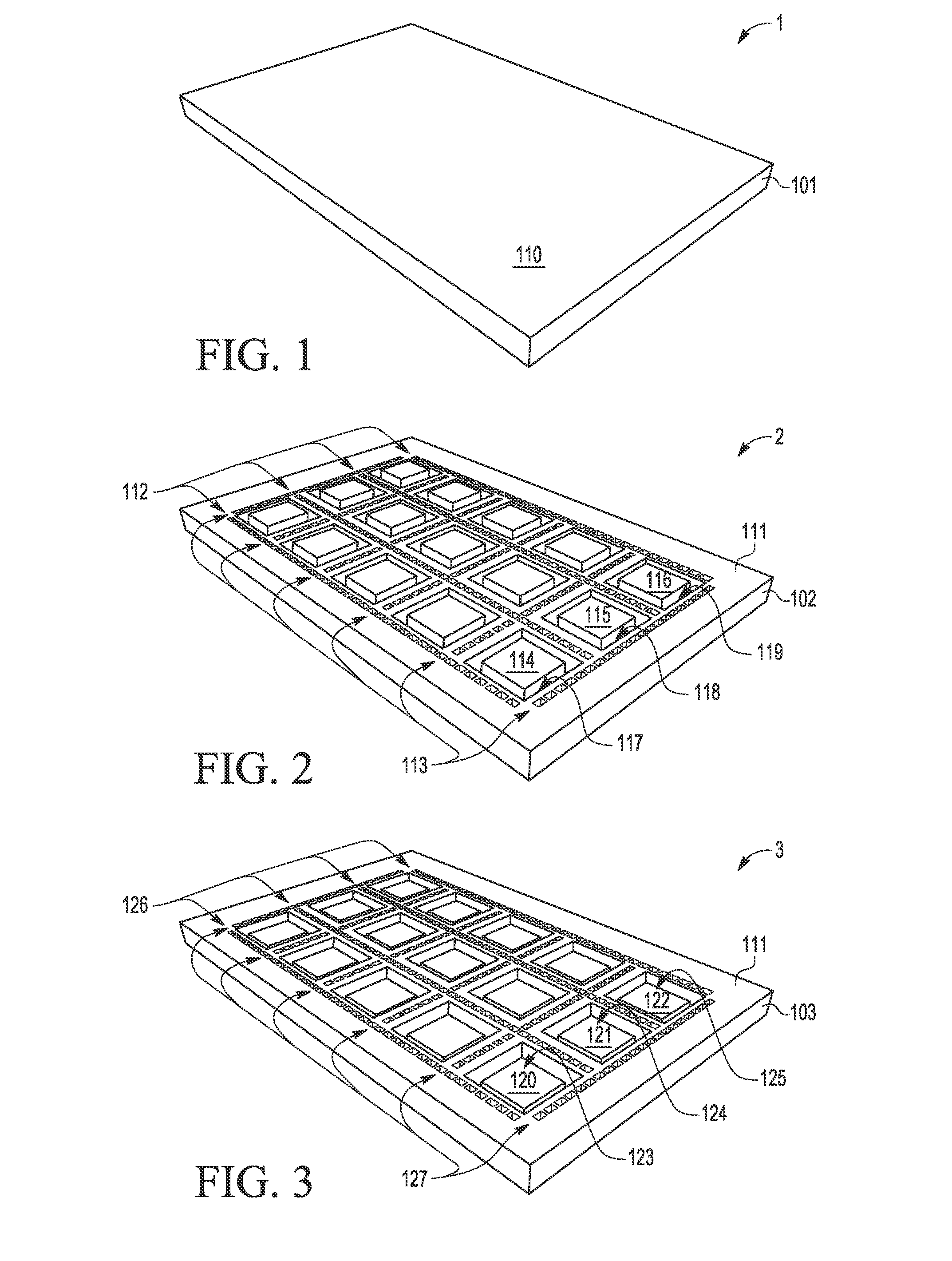
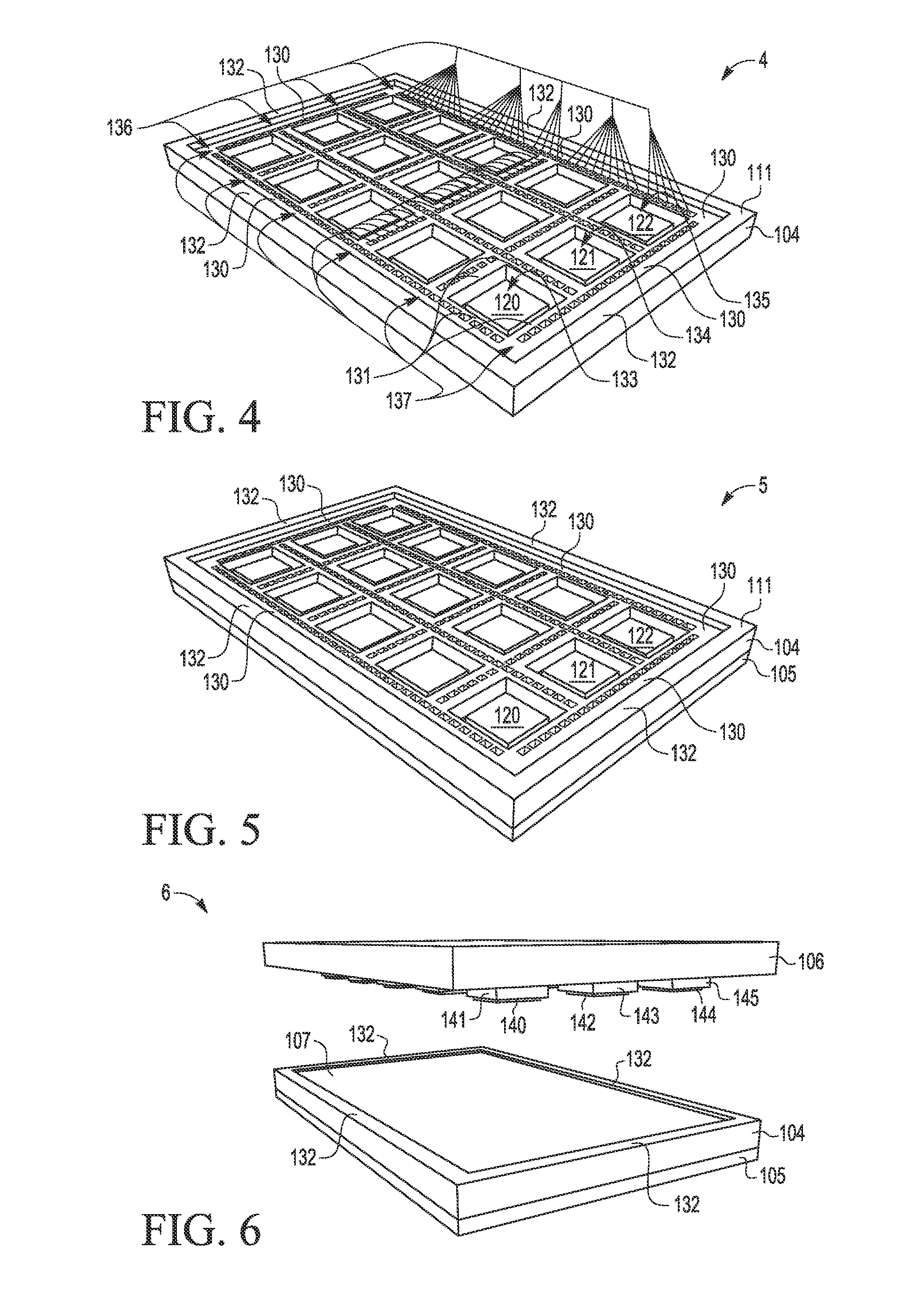
[0019]A method and apparatus are described for fabricating integrated circuit chips with low profile thermally enhanced compression mold packages (e.g., flip chip or ball grid array packages) with exposed heat spreader lids that are formed as an array of stamped or etched metal or other thermally conductive material which makes direct thermal contact with the integrated circuit chips which are encapsulated with compression molding compound prior to singulation. In selected embodiments, the heat spreader lid array eliminates the need for a lower mold cavity tool by providing a container for mold compound that seals the lid array to the substrate without requiring an adhesive. As formed, the heat spreader lid array includes recessed pedestal structures and surrounding pedestal recess areas which are suitable for wire bond and flip ship assemblies. The heat spreader lid arrays may also be formed with reduced metal in the intended saw singulation lines by forming recessed lid feet struc...


PUM


Abstract

A method and apparatus are provided for manufacturing a lead frame based thermally enhanced package (9) with exposed heat spreader lid array (96) designed to be optimized for compression mold encapsulation of an integrated circuit die (94) by including a perimeter reservoir regions (97r) in each heat spreader lid (96) for movement of mold compound (98) displaced during the mold compression process.

Description

BACKGROUND OF THE INVENTION[0001]1. Field of the Invention[0002]This invention relates to integrated circuit packages and a method of manufacturing same. In one aspect, the present invention relates to an integrated circuit package having an exposed lid heat spreader.[0003]2. Description of the Related Art[0004]As the density and complexity of integrated circuit devices increases and the size of such devices shrinks, significant challenges are posed in the design and packaging of these devices. One challenge is to provide a thermal path within the package to conduct heat away from the integrated circuit die, where conventional approaches for removing heat generated within the package typically use individual metal lids or heat spreaders that are separately applied to individual packaged units and then encapsulated with molding compound. The use of individual lids is not efficient for the manufacture of multiple integrated circuits in terms of the separate application requirements fo...

Claims


Application Information

Patent Timeline
Patent Type & Authority Applications(United States)
IPC IPC(8): H01L23/367H01L21/56H01L23/00
CPCH01L23/3675H01L24/13H01L21/565H01L21/561H01L24/81H01L23/4334H01L24/97H01L2224/48091H01L2224/73204H01L2224/73265H01L24/83H01L24/85H01L2224/13147H01L2224/2919H01L2224/45565H01L2224/73215H01L2224/73253H01L2224/83191H01L2924/181H01L2924/12042H01L2924/00014H01L24/48H01L2924/0665H01L2924/00H01L2224/45015H01L2924/207H01L2224/45099
Inventor HIGGINS, III, LEO M.
Owner NXP USA INC
Learn More