
Integrated circuit packaging system with stacking interconnect and method of manufacture thereof

a technology of integrated circuit packaging and interconnect, which is applied in the direction of electrical equipment, semiconductor devices, semiconductor/solid-state device details, etc., can solve the problems of reducing reliability and yield, causing good chips to be discarded along with failing chips, and reducing assembly process productivity

Active Publication Date: 2011-06-16
STATS CHIPPAC LTD
View PDF14 Cites 117 Cited by
  • Summary
  • Abstract
  • Description
  • Claims
  • Application Information

AI Technical Summary

Benefits of technology

The present invention provides a method for making an integrated circuit packaging system by fabricating a base package substrate and coupling a conductive column lead frame to it. This leads to a base package body with the conductive column and interconnect securing structure exposed on the top surface. The technical effect of this invention is to provide a more efficient and reliable integrated circuit packaging system that allows for better performance and reliability of the integrated circuit.

Problems solved by technology

The use of several chips in a single package does, however, tend to reduce both reliability and yield.
During post assembly testing, if just one chip in the multi-chip or chip stack package fails to meet the functional or performance specifications, the entire package fails, causing the good chip(s) to be discarded along with the failing chip.
As a result, multi-chip and chip stack package tend to lower the productivity from the assembly process.
Attempts to form area array type packages have met with other difficulties.
Positioning of the contacts within the array and alignment between the two stacked interfaces has proved a daunting problem.
As the number of interface contacts increases the critical alignment between the integrated circuit package interfaces becomes even more challenging.
Solutions to these problems have been long sought but prior developments have not taught or suggested any solutions and, thus, solutions to these problems have long eluded those skilled in the art.

Method used


Image

  • Integrated circuit packaging system with stacking interconnect and method of manufacture thereof
  • Integrated circuit packaging system with stacking interconnect and method of manufacture thereof
  • Integrated circuit packaging system with stacking interconnect and method of manufacture thereof

Examples


Embodiment Construction

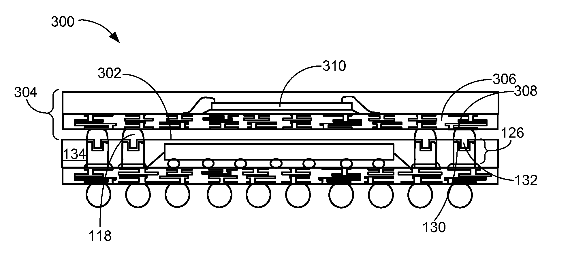
[0027]The following embodiments are described in sufficient detail to enable those skilled in the art to make and use the invention. It is to be understood that other embodiments would be evident based on the present disclosure, and that system, process, or mechanical changes may be made without departing from the scope of the present invention.

[0028]In the following description, numerous specific details are given to provide a thorough understanding of the invention. However, it will be apparent that the invention may be practiced without these specific details. In order to avoid obscuring the present invention, some well-known circuits, system configurations, and process steps are not disclosed in detail.

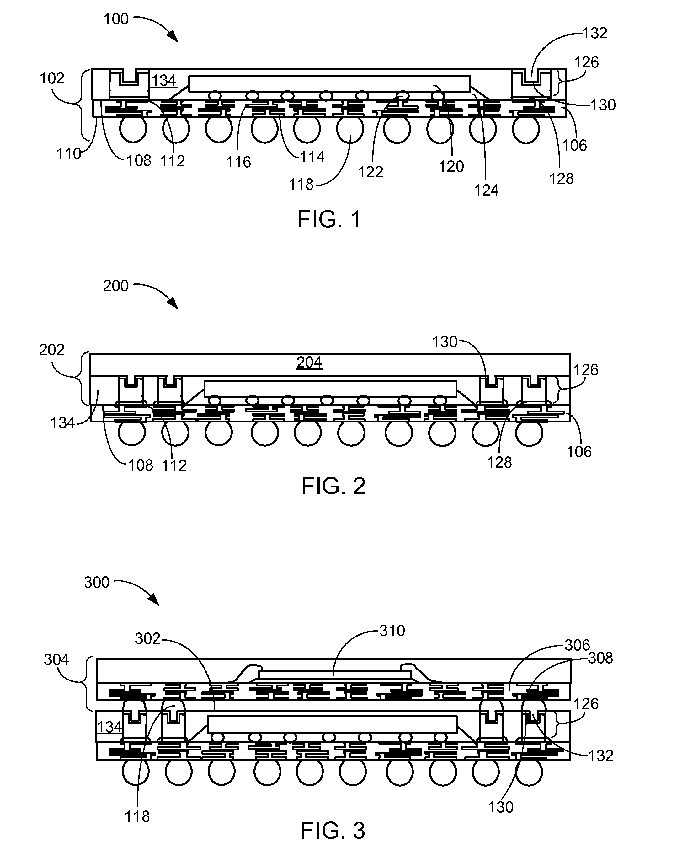
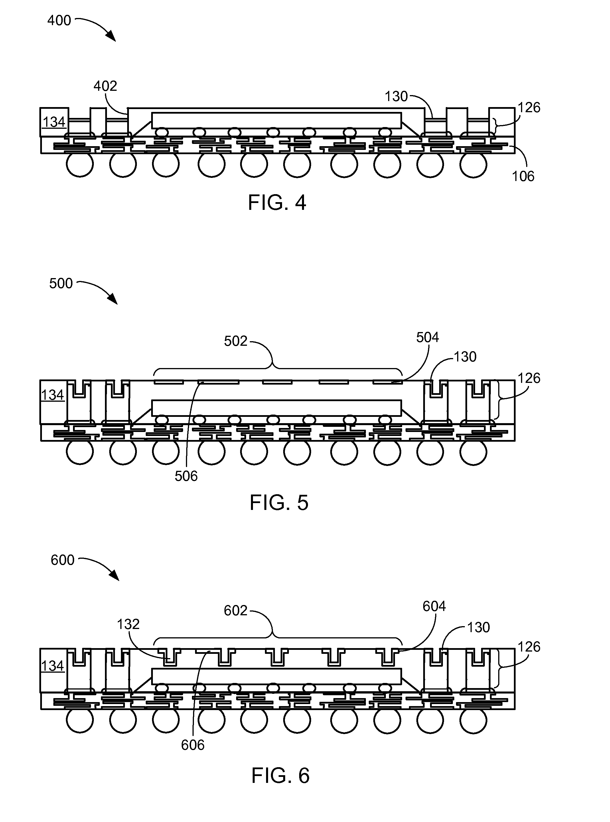
[0029]The drawings showing embodiments of the system are semi-diagrammatic and not to scale and, particularly, some of the dimensions are for the clarity of presentation and are shown exaggerated in the drawing FIGs. Similarly, although the views in the drawings for ease of descri...


PUM


Abstract

A method of manufacture of an integrated circuit packaging system includes: fabricating a base package substrate; coupling a conductive column lead frame to the base package substrate by: providing a lead frame support, patterning a conductive material on the lead frame support including forming an interconnect securing structure, and coupling the conductive material to the base package substrate; forming a base package body between the base package substrate and the conductive column lead frame; and removing the lead frame support from the conductive column lead frame for exposing the interconnect securing structure from the base package body.

Description

CROSS-REFERENCE TO RELATED APPLICATION(S)[0001]The present application contains subject matter related to co-pending U.S. patent application Ser. No. 12 / 488,089 filed Jun. 19, 2009. The related application is assigned to STATS ChipPAC Ltd. and the subject matter thereof is incorporated herein by reference thereto.TECHNICAL FIELD[0002]The present invention relates generally to an integrated circuit packaging system, and more particularly to a system for stacking integrated circuit packages.BACKGROUND ART[0003]The electronic industry continues to seek products that are lighter, faster, smaller, multi-functional, more reliable and more cost-effective. The advent of multi-function electronic devices, such as cell phones that are also game platforms, cameras, Internet portals, and music or video players, has brought immense pressure on the electronics device manufacturers and the manufacturing companies that support them.[0004]In an effort to meet such requirements, package assembly tech...

Claims


Application Information

Patent Timeline
Patent Type & Authority Applications(United States)
IPC IPC(8): H01L23/52H01L21/98H01L25/065
CPCH01L25/16H01L2225/1052H01L2224/48227H01L2924/3511H01L2225/107H01L2224/16225H01L2221/68381H01L2221/68359H01L25/50H01L25/105H01L24/73H01L24/48H01L24/32H01L24/16H01L23/49816H01L23/49811H01L21/6835H01L21/568H01L21/563H01L21/4853H01L2924/15311H01L2225/1058H01L2225/1023H01L2224/32225H01L2224/48091H01L2224/73204H01L2224/73265H01L2924/00014H01L2924/3512H01L2924/00H01L2924/00012H01L2924/14H01L2924/181H01L2924/1815H01L2224/131H01L2224/45099H01L2224/45015H01L2924/207H01L2924/014
Inventor CHO, NAMJUCHI, HEEJOSHIN, HANGILHUANG, RUICHOW, SENG GUANKUAN, HEAP HOE
Owner STATS CHIPPAC LTD
Learn More