
Piezoelectric power generation apparatus

a power generation apparatus and piezoelectric technology, applied in piezoelectric/electrostrictive/magnetostrictive devices, piezoelectric/electrostriction/magnetostriction machines, electrical devices, etc., can solve the problem of lowering the power generation efficiency of the piezoelectric power generation apparatus b>101/b>, and achieve the effect of improving the lowering of power generation efficiency and enhancing power generation efficiency

Active Publication Date: 2015-05-28
MURATA MFG CO LTD
View PDF5 Cites 13 Cited by
  • Summary
  • Abstract
  • Description
  • Claims
  • Application Information

AI Technical Summary

Benefits of technology

The present invention provides a piezoelectric power generation apparatus that can adjust sub vibration generated in a direction perpendicular to the main vibration used for power generation, and prevent a decrease in power generation efficiency caused by sub vibration. By adjusting the main vibration and sub vibration, the apparatus suppresses the sub vibration and improves power generation efficiency.

Problems solved by technology

This arises a risk that power generation efficiency of the piezoelectric power generation apparatus 101 is lowered.

Method used


Image

  • Piezoelectric power generation apparatus
  • Piezoelectric power generation apparatus
  • Piezoelectric power generation apparatus

Examples


Embodiment Construction

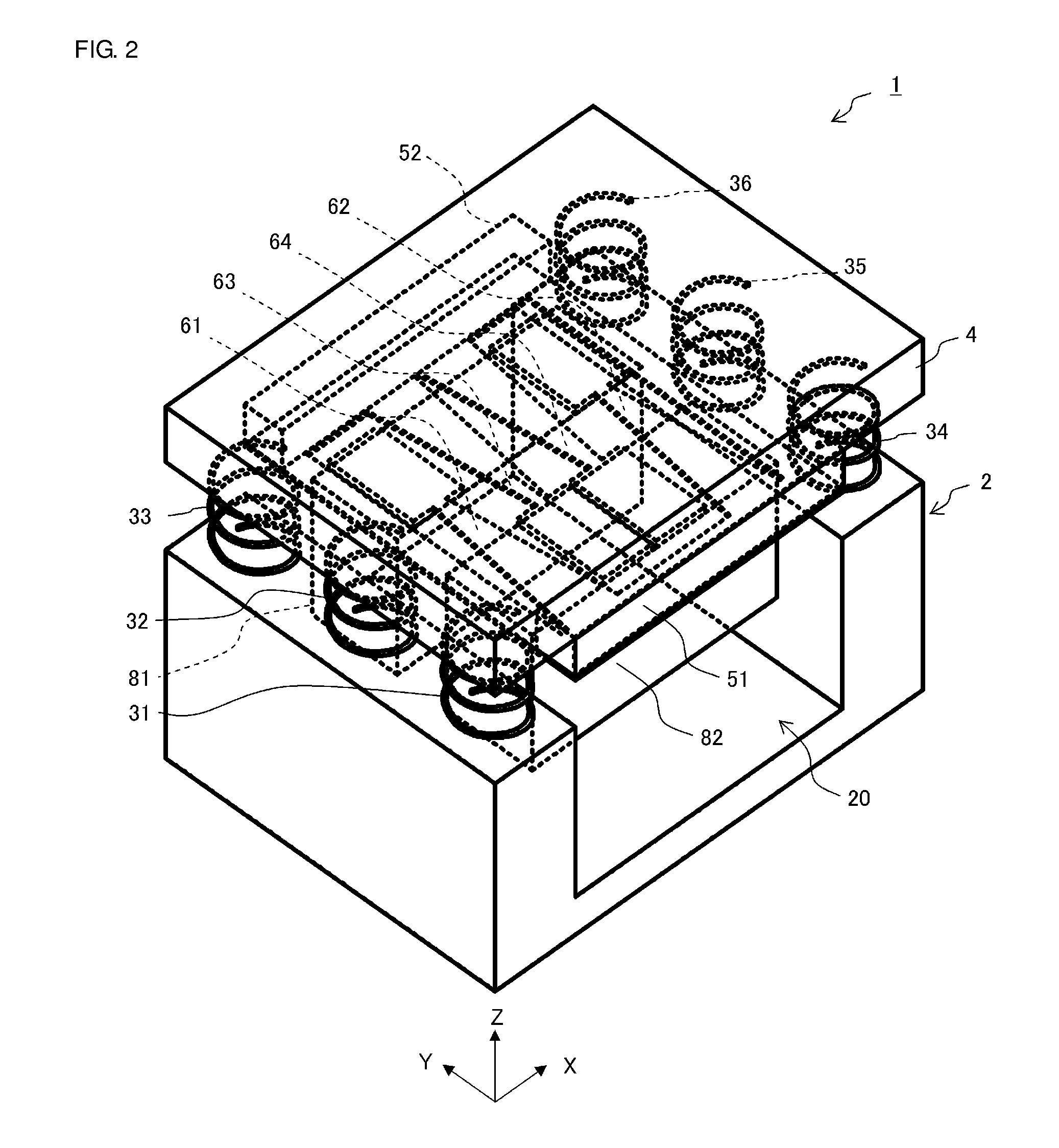
[0025]The configuration of a piezoelectric power generation apparatus1 according to a first embodiment of the invention is described with reference to FIGS. 1 to 6.

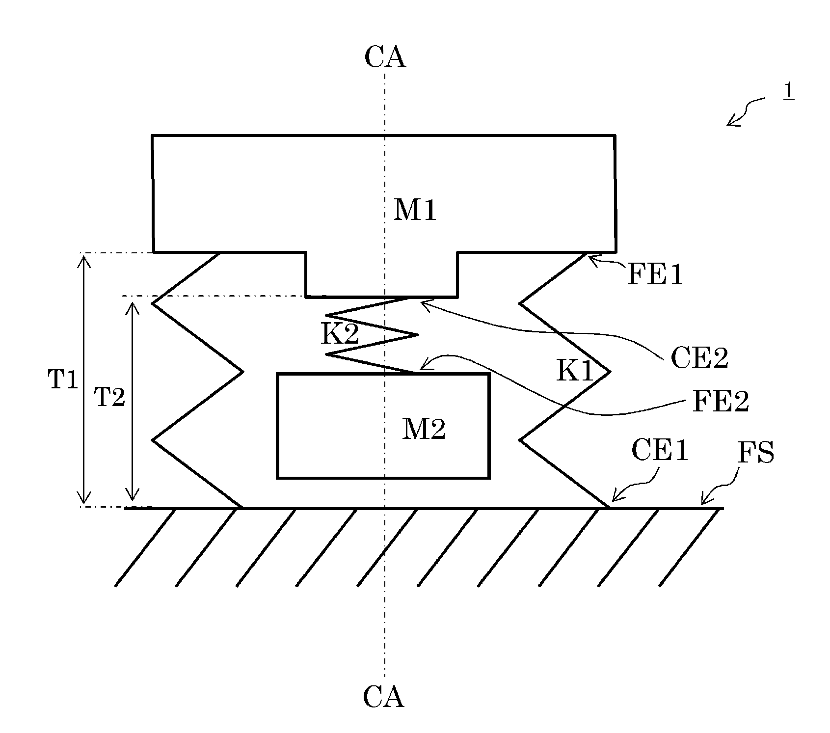
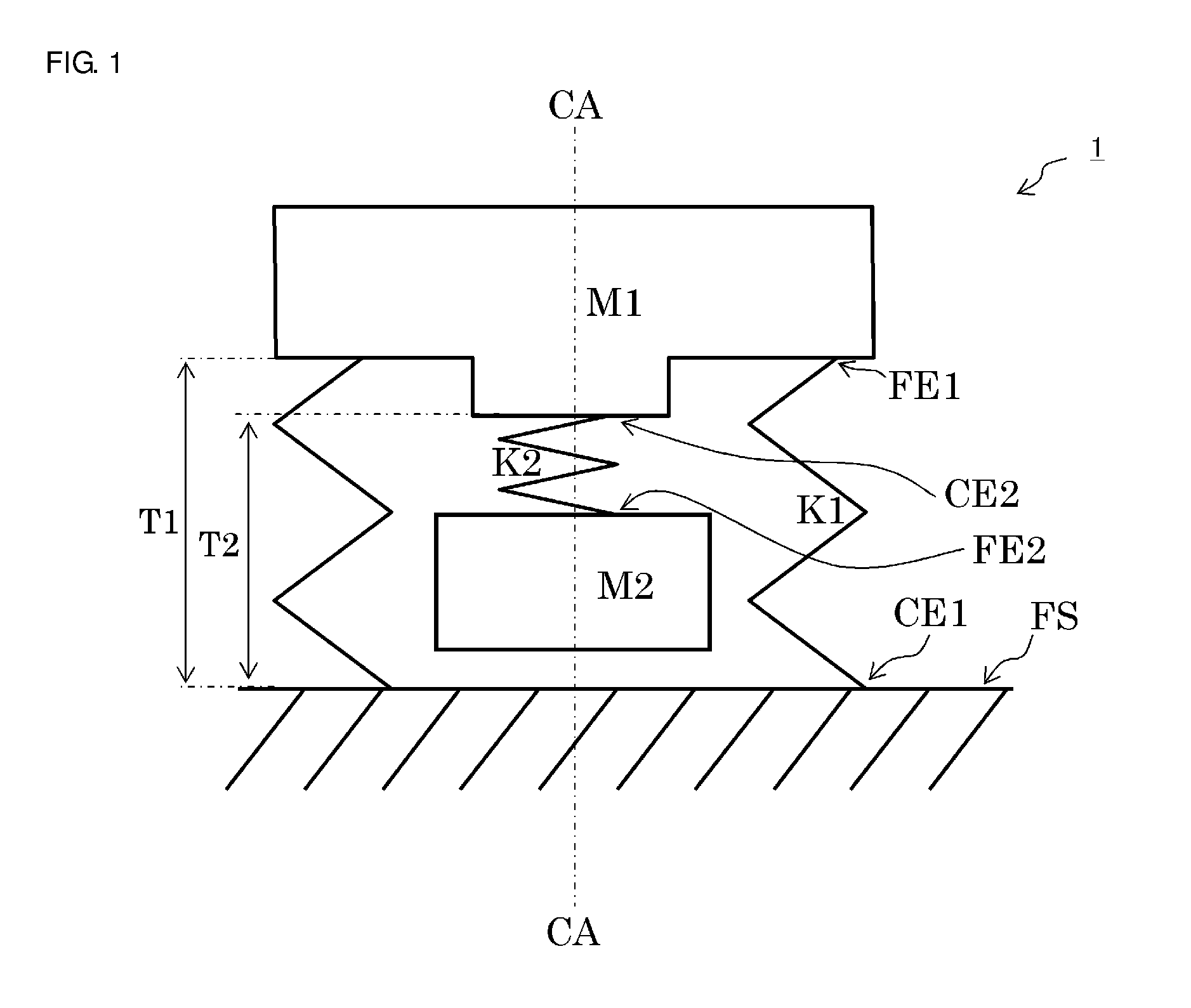
[0026]FIG. 1 is a schematic plan view illustrating the configuration of the piezoelectric power generation apparatus 1 according to the first embodiment of the invention. The piezoelectric power generation apparatus 1 in the first embodiment is configured by a first vibrating portion K1, a first weight portion M1, a second vibrating portion K2, and a second weight portion M2. The piezoelectric power generation apparatus 1 is arranged on a horizontal vibration surface FS.

[0027]The first vibrating portion K1 extends and contracts along an axis CA perpendicular to the vibration surface FS. The first vibrating portion K1 has a fixed end CE1 fixed to the vibration surface FS and a free end FE1 at the opposite side to the fixed end CE1. The first weight portion M1 is joined to the free end FE1 of the first vibrating portion K1....


PUM


Abstract

A piezoelectric power generation apparatus that includes a first vibrating portion having a fixed end and a free end, a first weight portion bonded to the free end of the first vibrating portion, a second vibrating portion having a fixed end bonded to the first weight portion and a free end, and including a vibrating plate and a piezoelectric element provided on the vibrating plate. A second weight portion is bonded to the free end of the second weight portion. In a state where the piezoelectric power generation apparatus is arranged on a vibration surface and is still, a position of the free end of the first vibrating portion and a position of the fixed end of the second vibrating portion in an axial direction perpendicular to the vibration surface are different from each other.

Description

CROSS REFERENCE TO RELATED APPLICATIONS[0001]The present application is a continuation of International application No. PCT / JP2013 / 069099, filed Jul. 12, 2013, which claims priority to Japanese Patent Application No. 2012-174612, filed Aug. 7, 2012, the entire contents of each of which are incorporated herein by reference.FIELD OF THE INVENTION[0002]The present invention relates to a piezoelectric power generation apparatus that converts vibration energy into electric energy using a piezoelectric effect.BACKGROUND OF THE INVENTION[0003]An existing piezoelectric power generation apparatus that generates electric power using a piezoelectric element has been proposed (for example, see paragraphs 0078 to 0080 and FIG. 12(a) in Patent Document 1).[0004]FIG. 10 is a view for explaining an example of the configuration of an existing piezoelectric power generation apparatus 101 by reference to description in Patent Document 1 and is a side view in a state where a part of the configuration o...

Claims


Application Information

Patent Timeline
Patent Type & Authority Applications(United States)
IPC IPC(8): H02N2/18
CPCH02N2/186H02N2/188H10N30/306
Inventor SAKAGUCHI, HITOSHIHORIGUCHI, CHIKAHIRO
Owner MURATA MFG CO LTD
Learn More