Electrical contactor

a contactor and electric technology, applied in the direction of contacts, switch power arrangements, electromagnetic relay details, etc., can solve the problems of life-threatening electrical shock hazards, unmetered electricity supplied, undesirable imbalance, etc., and achieve the effect of extending the life of the conta

Active Publication Date: 2015-05-28
JOHNSON ELECTRIC SA
View PDF5 Cites 2 Cited by
  • Summary
  • Abstract
  • Description
  • Claims
  • Application Information

AI Technical Summary

Benefits of technology

[0030]Controlling the opening and closing delay of the electrical contactor and limiting or preventing the electrical contact bounce, preferably utilizing a drive pulse having a truncated waveform allows the lifetime of the contacts to be extended, by limiting the damage caused to the contacts by erosion energy and arcing.

Problems solved by technology

In this welded-contact fault condition, un-metered electricity is supplied.
This can lead to a life-threatening electrical shock hazard, if the load connection that is thought to be disconnected is still live at 230 V AC.
The pull motion is generally much stronger that the push motion in such an arrangement, leading to an undesirable imbalance.

Method used


Image

  • Electrical contactor
  • Electrical contactor
  • Electrical contactor

Examples


Embodiment Construction

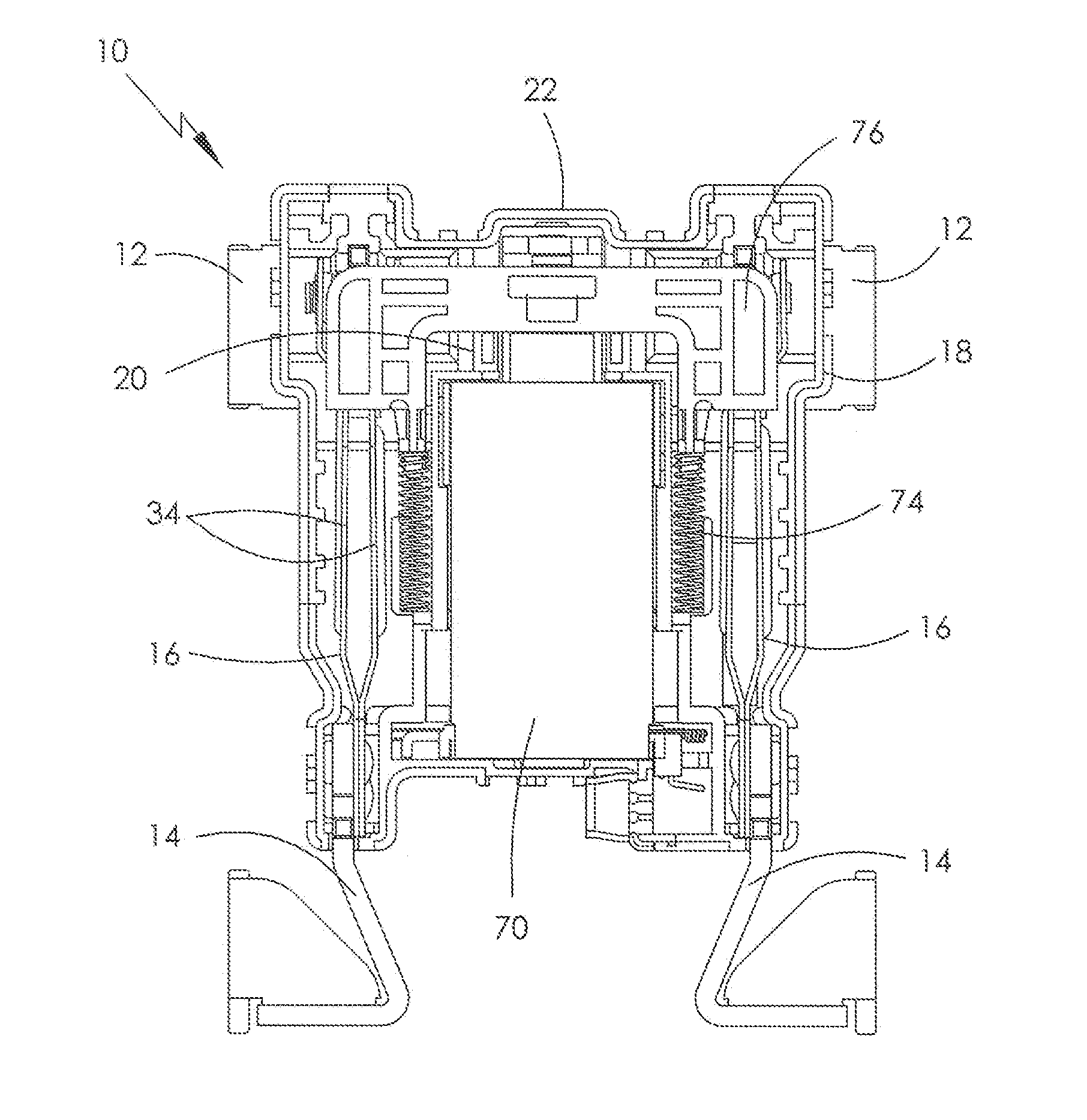
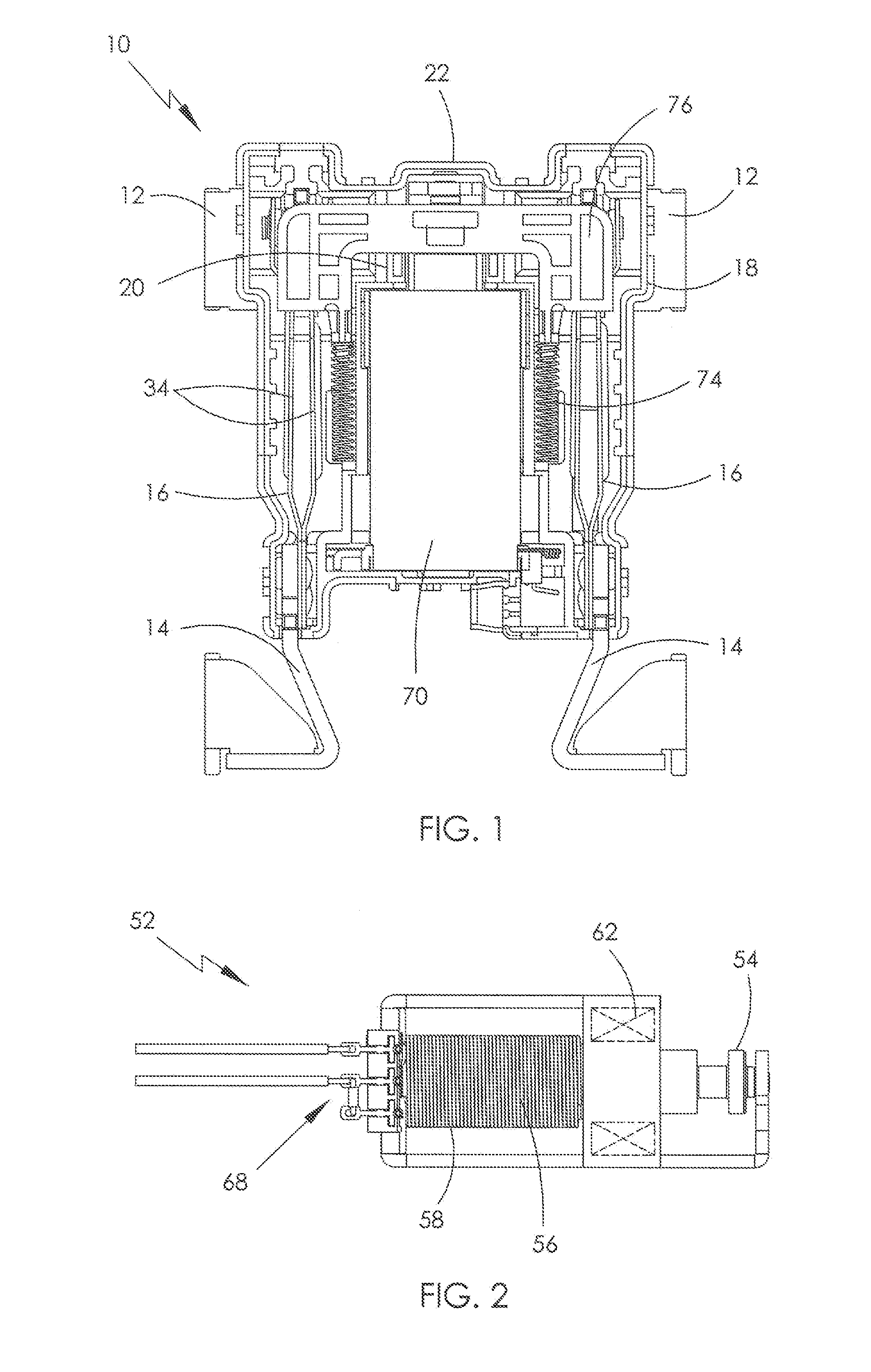
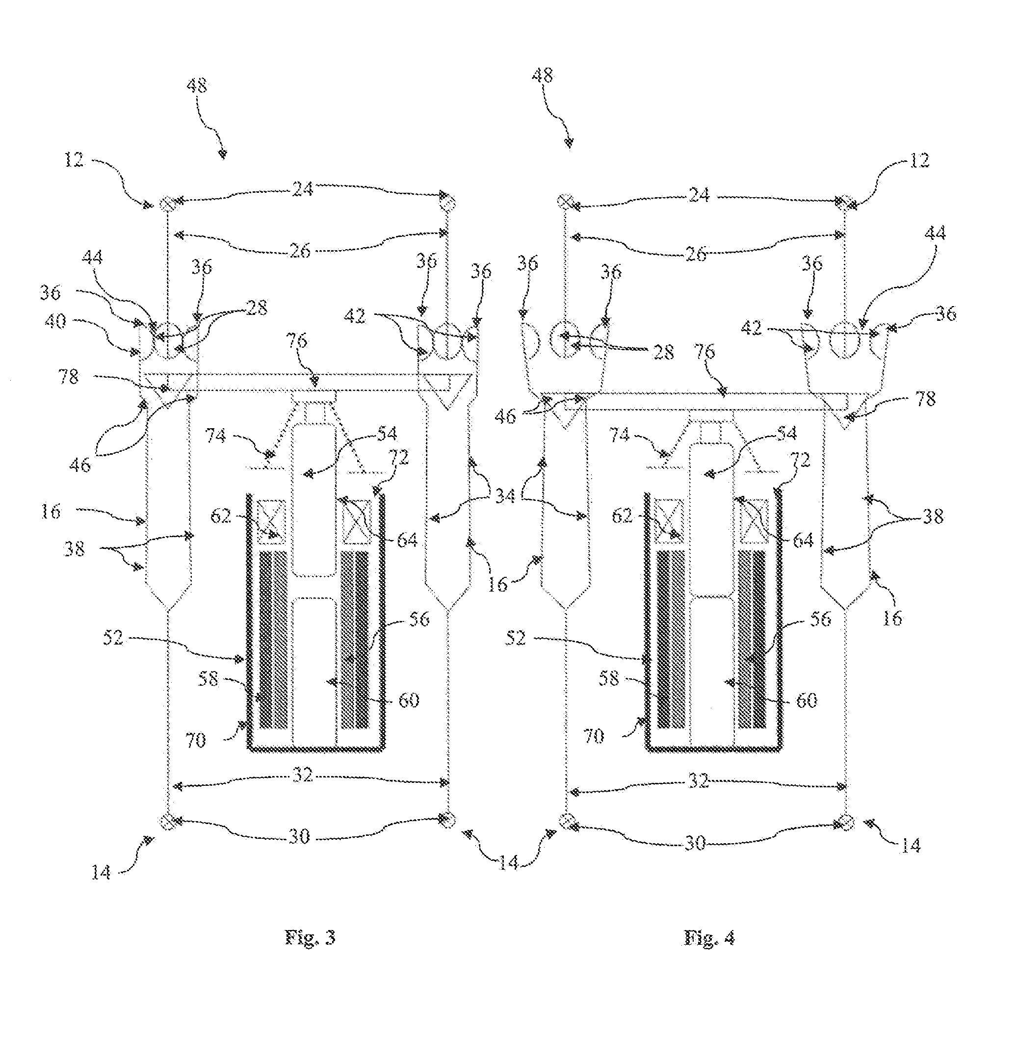
[0042]Referring firstly to FIGS. 1 to 4 of the drawings, there is shown a first embodiment of an electrical contactor, globally shown at 10 and in this case being a two-pole device, which comprises two outlet terminals 12, two feed terminals 14, and two pairs of movable arms 16.

[0043]The outlet terminals 12 and feed terminals 14 extend from a contactor housing 18, and are mounted to a housing base 20 and / or an upstanding perimeter wall 22 of the contactor housing 18. The housing cover is not shown for clarity.

[0044]Each outlet terminal 12 includes a first terminal pad 24 and a fixed, preferably electrically-conductive, first member 26 which extends from the first terminal pad 24 into the contactor housing 18. At least one, and in this case two, fixed electrical contacts 28 are provided at or adjacent to a distal end of each first member 26. In this instance, the fixed electrical contacts 28 are provided on opposing faces of the distal end of the fixed member 26, the contacts 28 pref...


PUM


Abstract

An electrical contactor is provided comprising a first terminal having a fixed member with at least one fixed electrical contact; a second terminal; at least one electrically-conductive movable arm in electrical communication with the second terminal and having a movable electrical contact thereon; and an AC dual-coil actuator having a first drive coil drivable to open and close the movable and fixed electrical contacts, and a second non-drive coil feedback connected to induce a reverse flux to temper and stabilize a net flux, thereby enabling control of a delay time of the opening and closing electrical contacts so as to be at or adjacent to a zero-crossing of an associated AC load current

Description

CROSS REFERENCE TO RELATED APPLICATIONS[0001]This non-provisional patent application claims priority under 35 U.S.C. §119(a) from Patent Application No. GB1402102.6 filed in The United Kingdom on Feb. 7, 2014, and from Patent Application No. GB1320859.0 filed in The United Kingdom on Nov. 26, 2013, the entire contents of which are hereby incorporated by reference.FIELD OF THE INVENTION[0002]The present invention relates to an electrical contactor, particularly but not necessarily exclusively for moderate AC switching contactors employed in modern electricity meters, so-called ‘smart meters’, for performing a load-disconnect function at normal domestic supply mains voltages, typically being 100 V AC to 250 V AC.BACKGROUND OF THE INVENTION[0003]The invention may also relate to an electrical contactor of a moderate, preferably alternating, current switch which may be subjected to a short-circuit fault condition requiring the contacts to not weld. In this welded-contact fault condition,...

Claims


Application Information

Patent Timeline
Patent Type & Authority Applications(United States)
IPC IPC(8): H01H7/16H01H1/50H01H9/30
CPCH01H7/16H01H1/50H01H9/30H01H47/02H01H50/14H01H50/44H01H1/54H01H47/22H01H50/58H01H50/86H01H50/54H01H50/24H01H51/2272H01H51/2245H01H2051/2218H01H50/642H01H47/18H01H47/223H01H50/56H01H50/68H01H3/28H01H9/56H01H2009/307
Inventor CONNELL, RICHARD ANTHONY
Owner JOHNSON ELECTRIC SA
Why Eureka
Try Eureka