Controlling density of dispensed printing material

a technology of printing material and density, applied in printing, manufacturing tools, additive manufacturing, etc., can solve the problems of printing head to jet or expel a drop of material, and much effort is invested

Active Publication Date: 2015-05-28
STRATASYS LTD
View PDF1 Cites 13 Cited by
  • Summary
  • Abstract
  • Description
  • Claims
  • Application Information

AI Technical Summary

Problems solved by technology

The pressure wave may cause the printing head to jet or expel a drop of the material.
In such application bubble formation in ink drops is conside...

Method used


Image

  • Controlling density of dispensed printing material
  • Controlling density of dispensed printing material
  • Controlling density of dispensed printing material

Examples


example

[0073]As discussed above, a relationship between gas bubble content and pulse timing may be determined empirically. The example below illustrates an empirical determination of gas bubble content when printing a 3D model.

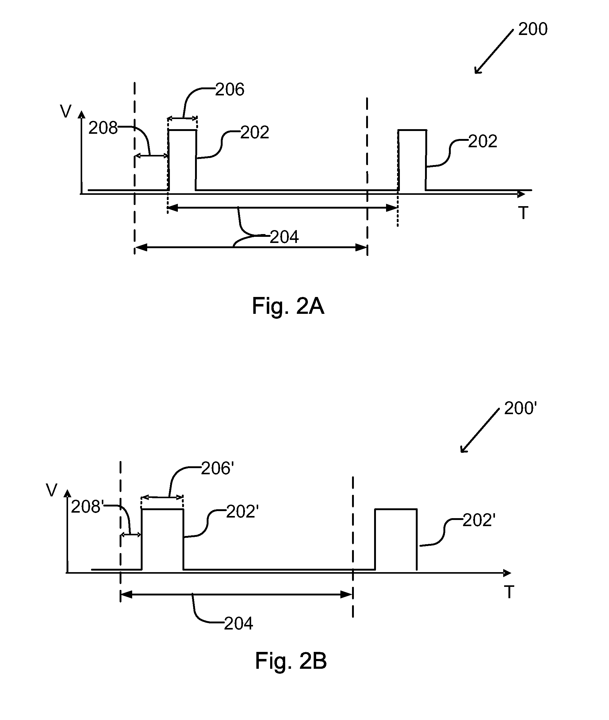
[0074]In order to introduce different amounts of gas bubbles inside the 3D model and to measure the gas bubble content, plano-parallel samples of approximately 1 cm thickness were printed from a transparent photopolymer, Objet Vero Clear™ RGD810, and jetted by an ALARIS™ 3D printer (both of Objet® Ltd., Rehovot, Israel). Different jetting (pulse) frequencies and different combinations of pulse widths and pulse delays were used in patterning the electric signal that was applied to a piezoelectric element of the printing head. Tested pulse timing pattern and changeable parameters are depicted schematically in FIGS. 3A and 3B.

[0075]Different building conditions (pulse timing) result in different and varying gas bubble content and, in turn, in different levels of translu...


PUM

PropertyMeasurementUnit
Fractionaaaaaaaaaa
Densityaaaaaaaaaa
Speedaaaaaaaaaa

Abstract

A printing method includes controlling timing parameters for application of electrical pulses to a piezoelectric nozzle of an inkjet printing head so as to dispense droplets of a material from the nozzle. The timing parameters are controlled to introduce gas bubbles into the droplets of material so as to reduce the density of the material to a selected density value that is less than a natural density of the material.

Description

FIELD OF THE INVENTION[0001]The present invention relates to printing using inkjet printing heads. More particularly, the present invention relates to controlling material density of material that is dispensed during printing.BACKGROUND OF THE INVENTION[0002]Three-dimensional (3D) printing is widely used for building objects, such as models or prototypes. In 3D printing, an object is constructed by deposition of material in a controlled manner so as to form the object. Instructions for guiding construction of the object may be derived from a digital representation of the object to be constructed. Such a digital representation may, for example, be generated by a computer-aided design or computer-aided manufacturing program or application.[0003]Commonly used 3D printers use inkjet printing heads for selectively dispensing material such as photopolymer material. The photopolymer material is deposited layer-by-layer to form a 3D model. Different photopolymer materials may be deposited t...

Claims


Application Information

Patent Timeline
IPC IPC(8): B41J2/045
CPCB41J2/04588B41J2/04581B41J2/04508B41J2/04573B41J2/04591B29C64/112
Inventor LIBINSON, ALEXANDER
Owner STRATASYS LTD
Why Eureka
Try Eureka