Light field processing method

a processing method and light field technology, applied in the field of light field processing methods, can solve the problems of a set of different plenoptic cameras that cannot be processed in time, and achieve the effect of improving the quality of light field data

Inactive Publication Date: 2015-05-28
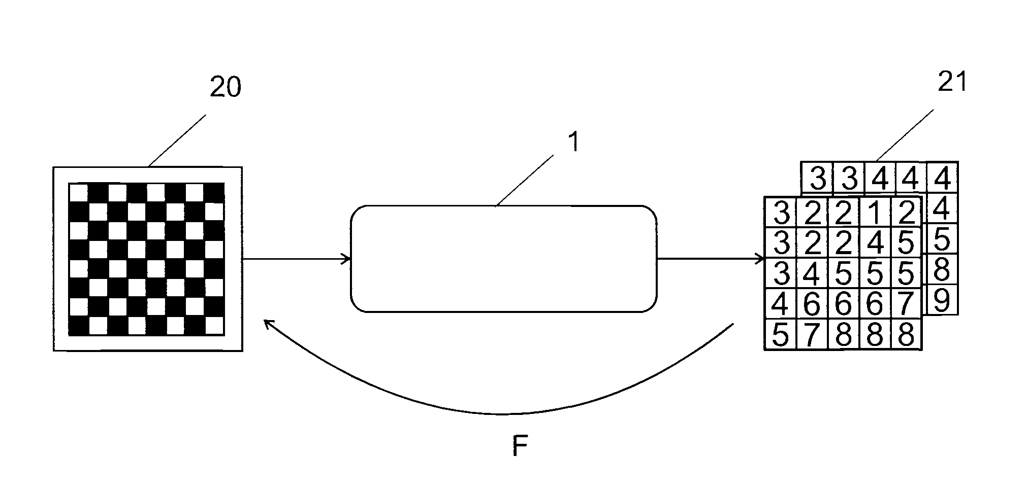
ECOLE POLYTECHNIQUE FEDERALE DE LAUSANNE (EPFL)
View PDF8 Cites 43 Cited by
  • Summary
  • Abstract
  • Description
  • Claims
  • Application Information

AI Technical Summary

Benefits of technology

[0010]The use of a camera independent representation for data representing a light field has the advantage for

Problems solved by technology

Since the format of captured information is different for each device, it is tedious to

Method used


Image

  • Light field processing method
  • Light field processing method
  • Light field processing method

Examples


Embodiment Construction

Definitions

[0027]Object Focal Plane: plane in a scene, which is parallel to a camera main lens and on which the plenoptic camera is focused.[0028]Image Focal Plane: plane within a camera, which is parallel to the camera main lens and where physical points lying on the Object Focal Plane are projected in focus on the Image Focal Plane.[0029]Focal Plane: when no mention of “Object” or “Image”, it means either one of the Object Focal Plane or Image Focal Plane.

Representations

[0030]A plenoptic function is a function, which describes a light field with multiple parameters as its arguments.

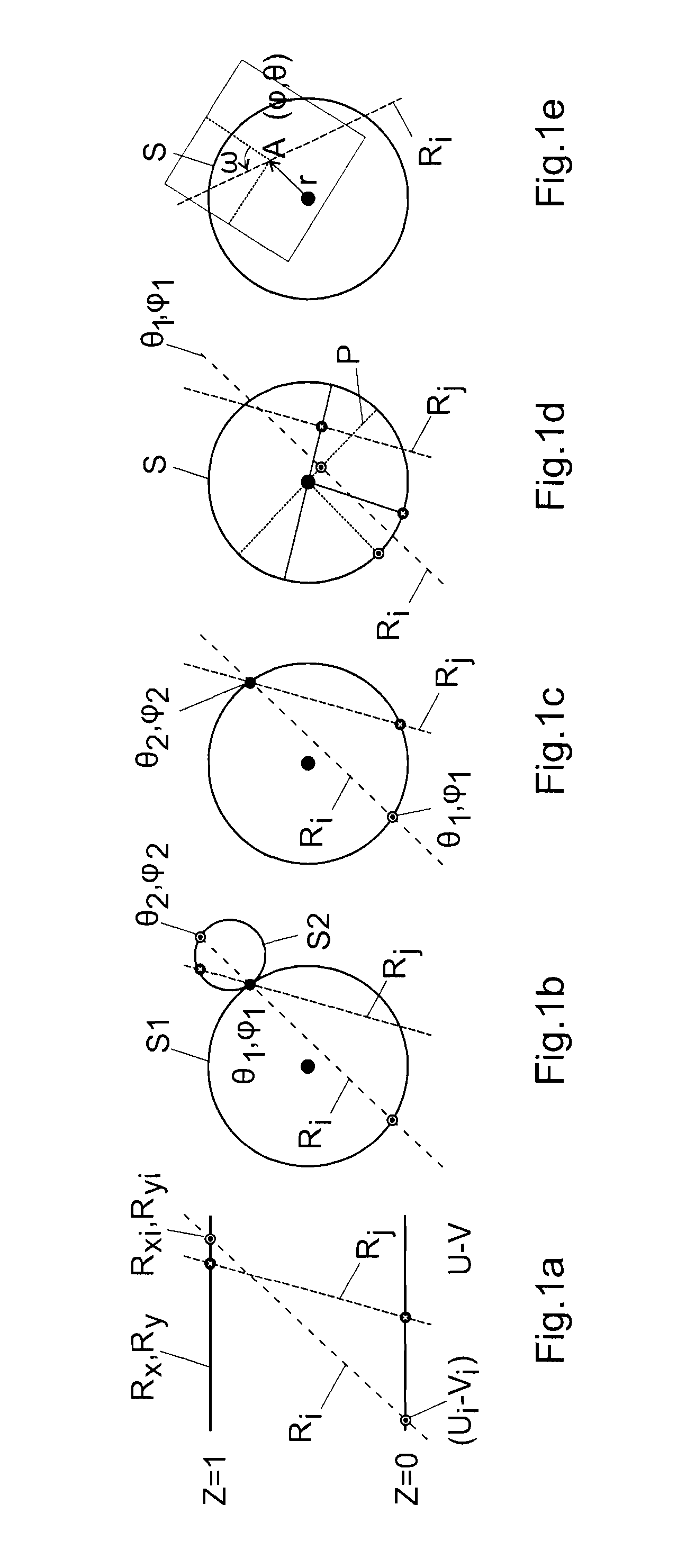
[0031]A typical plenoptic function represents the radiance of light emitted from a given position (x, y, z) in 3D space, and observed at a given position (u, v) on a 2D plane, at a given time and wavelength. A plenoptic function P, which represents the intensity of the light ray, takes the following form:

P=P(x,y,z,u,v,t,λ)

where t and λ are the observation time and the wavelength respectively.

[0032]Alter...


PUM


Abstract

A light field processing method for processing data corresponding to a light field, comprising:
    • capturing with a plenoptic camera initial data representing a light field in a format dependent from said plenoptic camera;
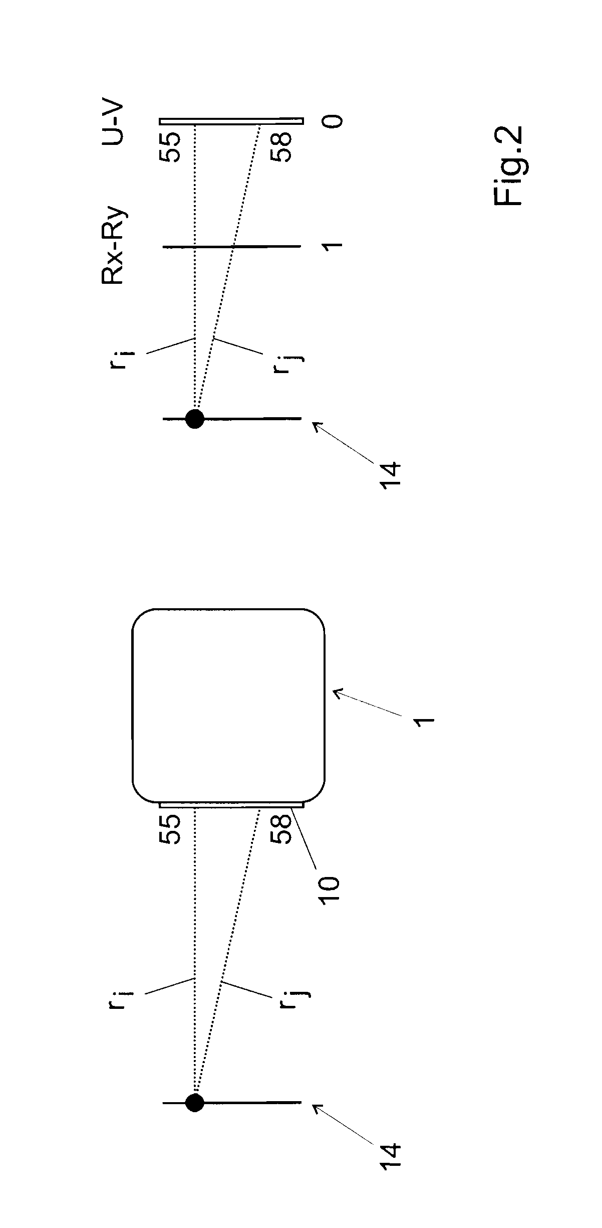
    • converting said initial data into converted data representing said light field in a camera independent format;
    • processing said converted data so as to generate processed data representing a different light field.

Description

FIELD OF THE INVENTION[0001]The present invention concerns a light field processing method.DESCRIPTION OF RELATED ART[0002]Devices to capture a light field are getting more and more popular. Light fields are often captured with plenoptic cameras. Popular examples of plenoptic camera include the Lytro camera for example.[0003]Each plenoptic camera generates data representing the captured light field in a camera dependent format. For example, the Lytro camera represents the light field by a series of matrix; each matrix includes a plurality of cells indicating the intensity of light reaching the micro lenses from various directions. The number of cells corresponds to the number of micro-lenses[0004]Since the format of captured information is different for each device, it is tedious to apply processing on light field data captured by a set of different plenoptic cameras.BRIEF SUMMARY OF THE INVENTION[0005]It is therefore an aim of the present invention to define a device independent pl...

Claims


Application Information

Patent Timeline
IPC IPC(8): H04N7/01H04N5/232H04N13/232H04N13/30
CPCH04N5/23229H04N7/01G06T2207/10052G06T19/006G06T2200/21G06T7/55H04N13/232H04N13/30H04N13/139H04N23/80
Inventor RIME, LAURENTARULRAJ, BERNARD M.NISHIDA, KEISHI
Owner ECOLE POLYTECHNIQUE FEDERALE DE LAUSANNE (EPFL)
Why Eureka
Try Eureka