Image pickup apparatus and image pickup method

a technology of image pickup and image, which is applied in the field of image pickup apparatus and image pickup method, can solve the problems of increasing the size of the whole image pickup apparatus, and achieve the effect of not complicated configuration and composition of the image pickup apparatus

Inactive Publication Date: 2010-03-18
SONY CORP
View PDF6 Cites 98 Cited by
  • Summary
  • Abstract
  • Description
  • Claims
  • Application Information

AI Technical Summary

Benefits of technology

[0088]According to the image pickup apparatus or the image pickup method according to the first mode of the invention, the microlens array section of which the focal length is variable in response to an applied voltage is included, so image pickup mode switching between the first image pickup mode in which incident light into the microlens array section forms an image without changing its direction on the image pickup device, and the second image pickup mode in which incident light forms an image on the microlenses, and then the image is projected on the image pickup device can be easily performed. Moreover, a common image pickup optical system is used in these two image pickup modes, so the configuration and composition of the image pickup apparatus are not complicated.
[0089]Moreover, according to the image pickup apparatus or the image pickup method according to the second mode of the invention, the polarizing plate and the polarization direction variable device are arranged between the image pickup lens and the microlens array section, so image pickup switching between the first image pickup mode in which incident light into the microlens array section forms an image without changing its direction on the image pickup device, and the second image pickup mode in which incident light forms an image on the microlenses, and then the image is projected on the image pickup device can be easily performed by the activation of the polarization direction variable device. Moreover, a common image pickup optical system is used in these two image pickup modes, so the configuration and composition of the image pickup apparatus are not complicated.

Problems solved by technology

Therefore, in the case of attempting to use two image pickup modes by switching between them, there is an issue that the configuration and composition of the image pickup apparatus are complicated to cause an increase in the size of the whole image pickup apparatus.

Method used


Image

  • Image pickup apparatus and image pickup method
  • Image pickup apparatus and image pickup method
  • Image pickup apparatus and image pickup method

Examples


first embodiment

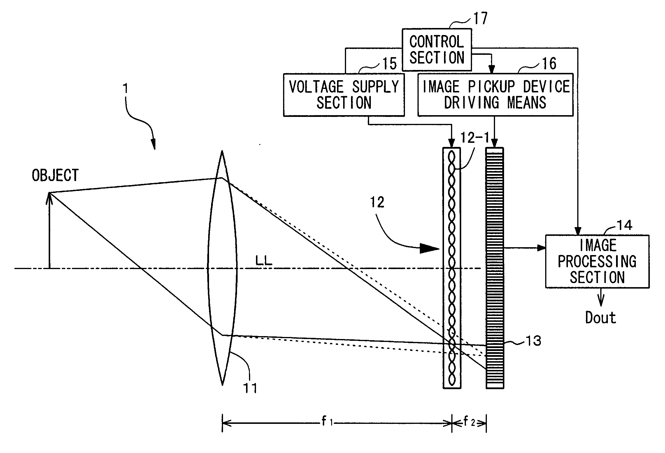
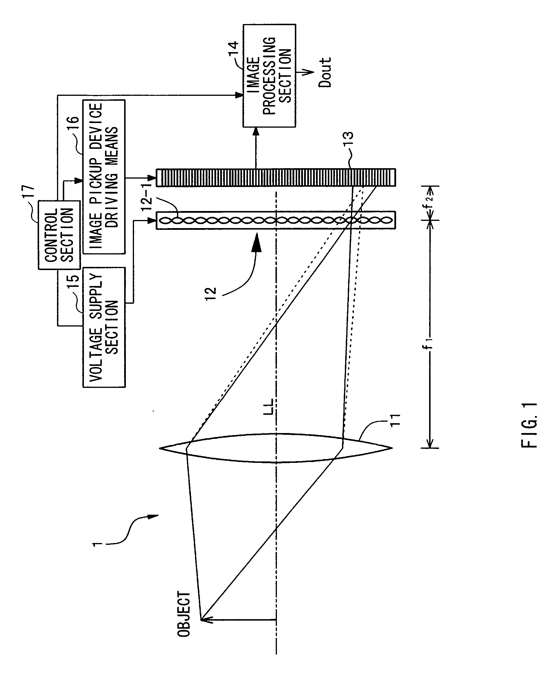
[0104]A first embodiment relates to an image pickup apparatus and an image pickup method according to a first mode of the invention. More specifically, an image pickup apparatus of the first embodiment has a first configuration and a 4Ath configuration. FIG. 1 illustrates a conceptual diagram of an image pickup apparatus 1 of the first embodiment.

[0105]The image pickup apparatus 1 of the first embodiment picks up an image of an object subjected to image pickup to output image pickup data Dout, and includes:

[0106](A) an image pickup lens 11,

[0107](B) a microlens array section 12 where light passing through the image pickup lens 11 enters, and

[0108](C) an image pickup device (an image pickup means) 13 sensing light emitted from the microlens array section 12.

[0109]The focal length of each of microlenses 12-1 constituting the microlens array section 12 is variable in response to an applied voltage.

[0110]Herein, in the image pickup apparatus 1 of the first embodiment, image pickup is pe...

second embodiment

[0145]The second embodiment is a modification of the first embodiment, and more specifically, the second embodiment relates to a third configuration and a 4Ath configuration. FIG. 5 illustrates a conceptual diagram of an image pickup apparatus of the second embodiment, and an image pickup apparatus 2 of the second embodiment further includes a driving means 18 changing a distance between the microlens array section 12 and the image pickup device (the image pickup means) 13 while maintaining a fixed distance between the image pickup lens 11 and the microlens array section 12. Then, in the case where a mismatch between the F-number of the image pickup lens 11 and the F-number of each of microlenses constituting the microlens array section 12 occurs, a voltage applied from the voltage supply section 15 to the microlens array section 12 is changed, and the distance between the microlens array section 12 and the image pickup device 13 is changed by the driving means 18. The driving means...

third embodiment

[0153]The third embodiment is also a modification of the first embodiment. In the third embodiment, a 4Bth configuration is used. In other words, as illustrated in a conceptual diagram in FIG. 9, when a three-dimensional Gaussian space with an optical axis of an image pickup apparatus 3 as a Z axis is defined, a polarizing plate 30 emitting polarized light to an X-axis direction and a polarization direction variable device 40 are arranged between the image pickup lens 11 and a microlens array section 312. Then, when a liquid crystal lens array constituting the microlens array section 312 functions as a lens, each microlens does not have power (optical power) in the X-axis direction and has power (optical power) in a Y-axis direction. That is, the liquid crystal lens array constitutes the microlens array section 312 having an anisotropic focal length on the Z axis as a center. In other words, each of liquid crystal lenses constituting the liquid crystal lens array forms a microlens h...


PUM


Abstract

An image pickup apparatus having a simple configuration and being capable of performing switching between an image pickup mode based on a light field photography technique and a normal high-resolution image pickup mode is provided. The image pickup apparatus includes an image pickup lens 11, a microlens array section 12 where light passing through the image pickup lens 11 enters, and an image pickup device 13 sensing light emitted from the microlens array section 12, and the focal length of each of microlenses constituting the microlens array section 12 is variable in response to an applied voltage.

Description

TECHNICAL FIELD[0001]The present invention relates to an image pickup apparatus and an image pickup method, more specifically to an image pickup apparatus and an image pickup method capable of switching between two image pickup modes, for example, an image pickup mode based on a light field photography technique and a normal high-resolution image pickup mode.BACKGROUND ART[0002]Various image pickup apparatuses have been hitherto proposed and developed. Moreover, an image pickup apparatus performing predetermined image processing on an image pickup signal obtained by image pickup to output the image pickup signal has been proposed. For example, Patent Document 1 and Non-patent Document 1 propose an image pickup apparatus using a technique called light field photography. The image pickup apparatus includes an image pickup lens, a microlens array, a light-sensing device and an image processing section, and an image pickup signal obtained from the light-sensing device includes the inten...

Claims


Application Information

Patent Timeline
Patent Type & Authority Applications(United States)
IPC IPC(8): H04N13/02H04N5/225H04N5/228G02B3/00G02B3/14G03B15/00G03B17/12G03B35/08H04N1/028H04N5/335
CPCG02B3/0056G02B3/0075H04N13/0232G03B15/00H04N5/2254G02B3/14H04N13/232H04N13/229H04N23/957H04N23/60H04N23/667
Inventor KAJIHARA, JUNJIYAMAMOTO, KENJIICHIMURA, ISAO
Owner SONY CORP
Why Eureka
Try Eureka