

Imaging lens
- Summary
- Abstract
- Description
- Claims
- Application Information
AI Technical Summary
Benefits of technology
Problems solved by technology
Method used
Image

Examples
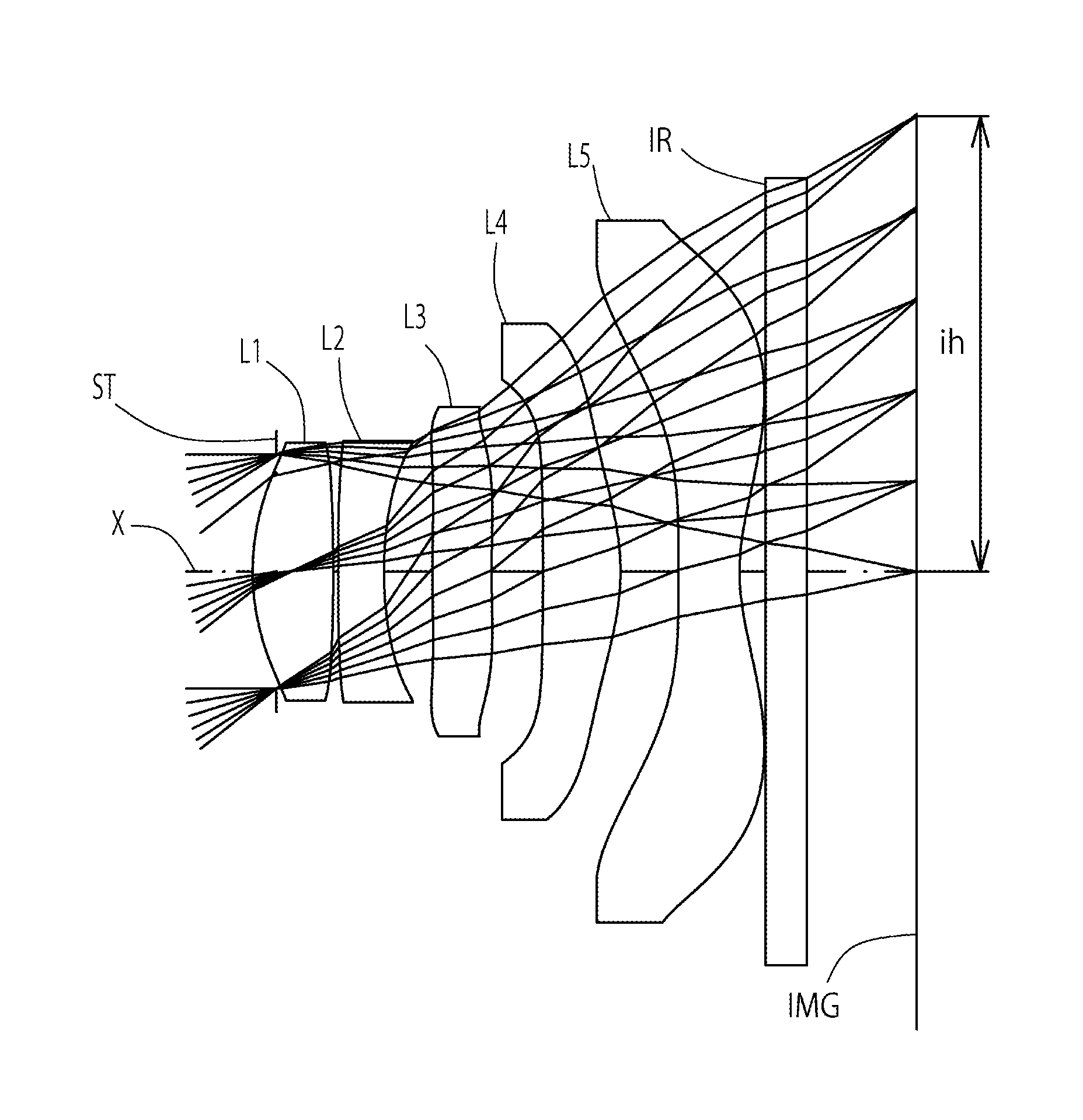
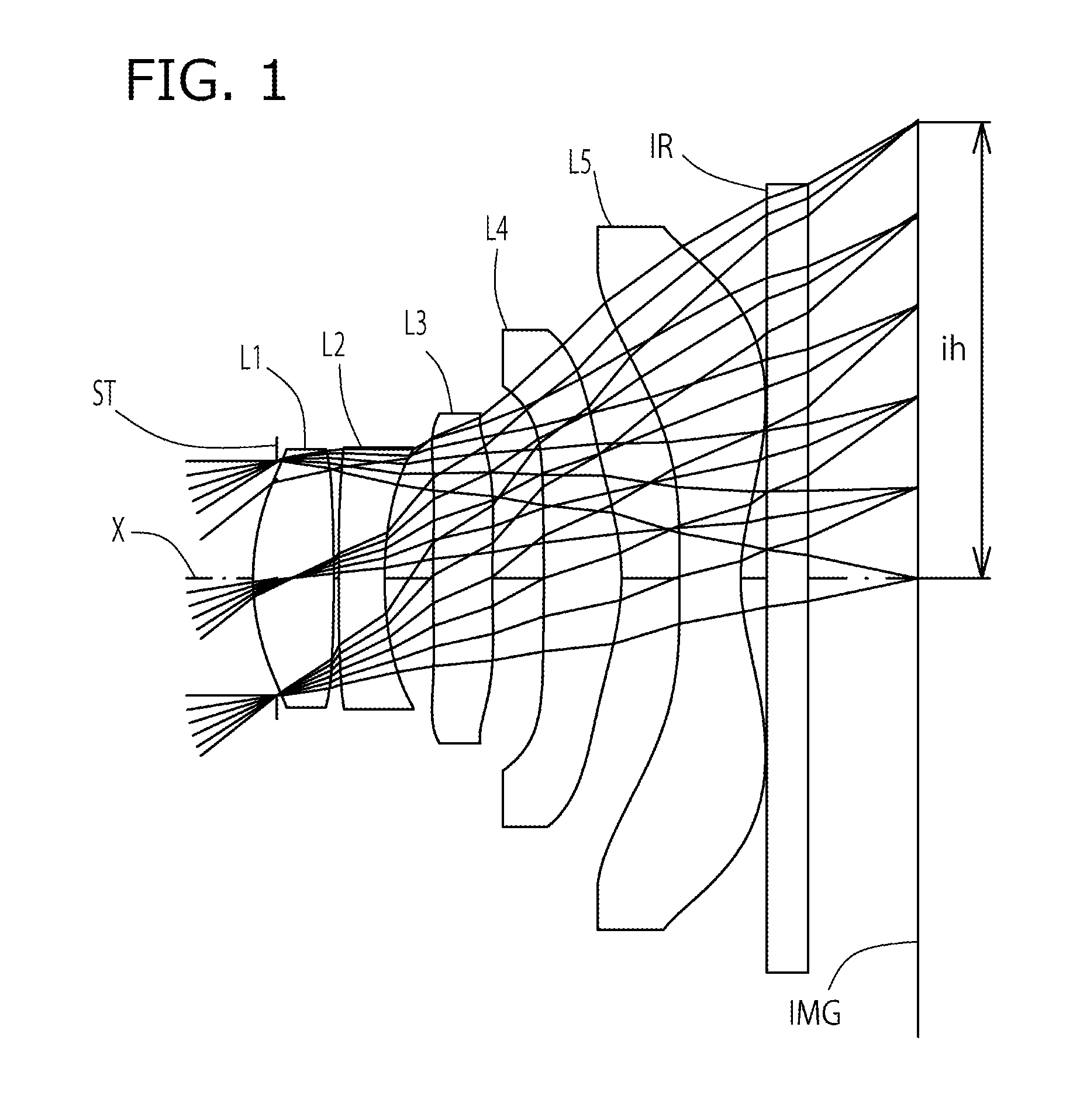
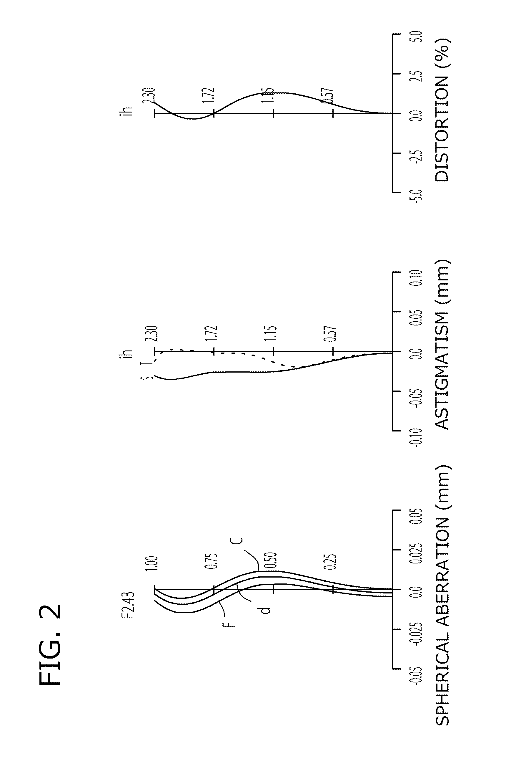
example 1
[0097]The basic lens data of Example 1 is shown in Table 1 below.
TABLE 1Example 1in mmf = 2.87Fno = 2.43ω(°) = 38.5ih = 2.30TLA = 3.28bf = 0.82Surface DataCurvatureSurfaceRefractiveAbbeSurface No. iRadius rDistance dIndex NdNumber vd(Object Surface)InfinityInfinity1 Infinity−0.120(Stop)2*1.1940.4071.54455.573*−6.8100.0254*93.0110.2301.63523.975*1.8710.2456*6.3260.2991.54455.577*7.1120.2598*−15.2080.3911.54455.579*−1.1800.29310* −25.4660.3071.53556.1611* 1.0830.13012 Infinity0.2101.51764.2013 Infinity0.552Image PlaneInfinityConstituent Lens DataLensStart SurfaceFocal Length121.90224−3.0103692.764482.329510−1.936Aspheric Surface Data2nd Surface3rd Surface4th Surface5th Surface6th Surfacek0.000E+000.000E+000.000E+005.002E+000.000E+00A4−2.874E−021.756E−011.767E−01−7.087E−02−3.749E−01A6−1.916E−01−3.582E−012.466E−013.872E−012.033E−01A85.894E−01−9.637E−01−2.274E+00−7.482E−013.965E−01A10−1.646E+001.218E+003.332E+003.652E−010.000E+00A120.000E+000.000E+000.000E+000.000E+000.000E+00A140.000E+0...
example 2
[0101]The basic lens data of Example 2 is shown in Table 3 below.
TABLE 3Example 2in mmf = 2.89Fno = 2.45ω(°) = 38.1ih = 2.30TLA = 3.27bf = 0.81Surface DataCurvatureSurfaceRefractiveAbbeSurface No. iRadius rDistance dIndex NdNumber vd(Object Surface)InfinityInfinity1 Infinity−0.120(Stop)2*1.1610.3811.54455.573*−6.2260.0254*98.9060.2301.63523.975*1.8270.2626*12.0120.2861.54455.577*15.7000.2898*−9.8570.3931.54455.579*−1.1890.29210* −15.7560.3071.53556.1611* 1.13610.13012 Infinity0.2101.51764.2013 Infinity0.538Image PlaneInfinityConstituent Lens DataLensStart SurfaceFocal Length121.83324−2.9343691.538482.448510−1.970Aspheric Surface Data2nd Surface3rd Surface4th Surface5th Surface6th Surfacek0.000E+000.000E+000.000E+000.000E+004.868E+00A4−2.823E−021.817E−011.751E−01−7.063E−02−3.843E−01A6−1.912E−01−3.581E−012.621E−013.935E−012.031E−01A85.588E−01−9.972E−01−2.204E+00−7.432E−013.956E−01A10−1.865E+001.179E+003.394E+003.229E−010.000E+00A120.000E+000.000E+000.000E+000.000E+000.000E+00A140.000E...
example 3
[0105]The basic lens data of Example 3 is shown in Table 5 below.
TABLE 5Example 3in mmf = 2.87Fno = 2.43ω(°) = 38.4ih = 2.30TLA = 3.28bf = 0.81Surface DataCurvatureSurfaceRefractiveAbbeSurface No. iRadius rDistance dIndex NdNumber vd(Object Surface)InfinityInfinity1 Infinity−0.120(Stop)2*1.2170.3981.54455.573*−11.0260.0254*18.8030.2301.63523.975*1.8950.2446*4.5790.2681.54455.577*5.6120.3188*−13.6520.3661.54455.579*−1.1860.30310* −32.3280.3191.53556.1611* 1.0800.13012 Infinity0.2101.51764.2013 Infinity0.538Image PlaneInfinityConstituent Lens DataLensStart SurfaceFocal Length122.03924−3.3363641.881482.363510−1.948Aspheric Surface Data2nd Surface3rd Surface4th Surface5th Surface6th Surfacek0.000E+000.000E+000.000E+004.884E+000.000E+00A4−2.363E−021.721E−011.735E−01−7.584E−02−3.923E−01A6−1.964E−01−3.654E−012.194E−013.681E−011.870E−01A85.783E−01−9.929E−01−2.366E+00−8.029E−013.952E−01A10−1.515E+009.838E−013.204E+004.585E−010.000E+00A120.000E+000.000E+000.000E+000.000E+000.000E+00A140.000E+...
PUM
 Abstract
Description
Claims
Application Information