Apparatus and methods for filling teeth and root canals

Active Publication Date: 2015-05-28
SONENDO
View PDF0 Cites 49 Cited by
  • Summary
  • Abstract
  • Description
  • Claims
  • Application Information

AI Technical Summary

Benefits of technology

[0014]For purposes of this summary, certain aspects, advantages, and novel features of certain disclosed inventions are summarized. It is to be understood that not necessarily all such advantages may be achieved in accordance with any particular embodiment of the invention. Thus, for example, those skilled in the art will recognize that the inventions discl

Problems solved by technology

Such procedures are often painful for the patient and frequently do not remove all the diseased material.
Howeve

Method used


Image

  • Apparatus and methods for filling teeth and root canals
  • Apparatus and methods for filling teeth and root canals
  • Apparatus and methods for filling teeth and root canals

Examples


Embodiment Construction

I. Overview of System and Methods

A. Overview of Various System Components

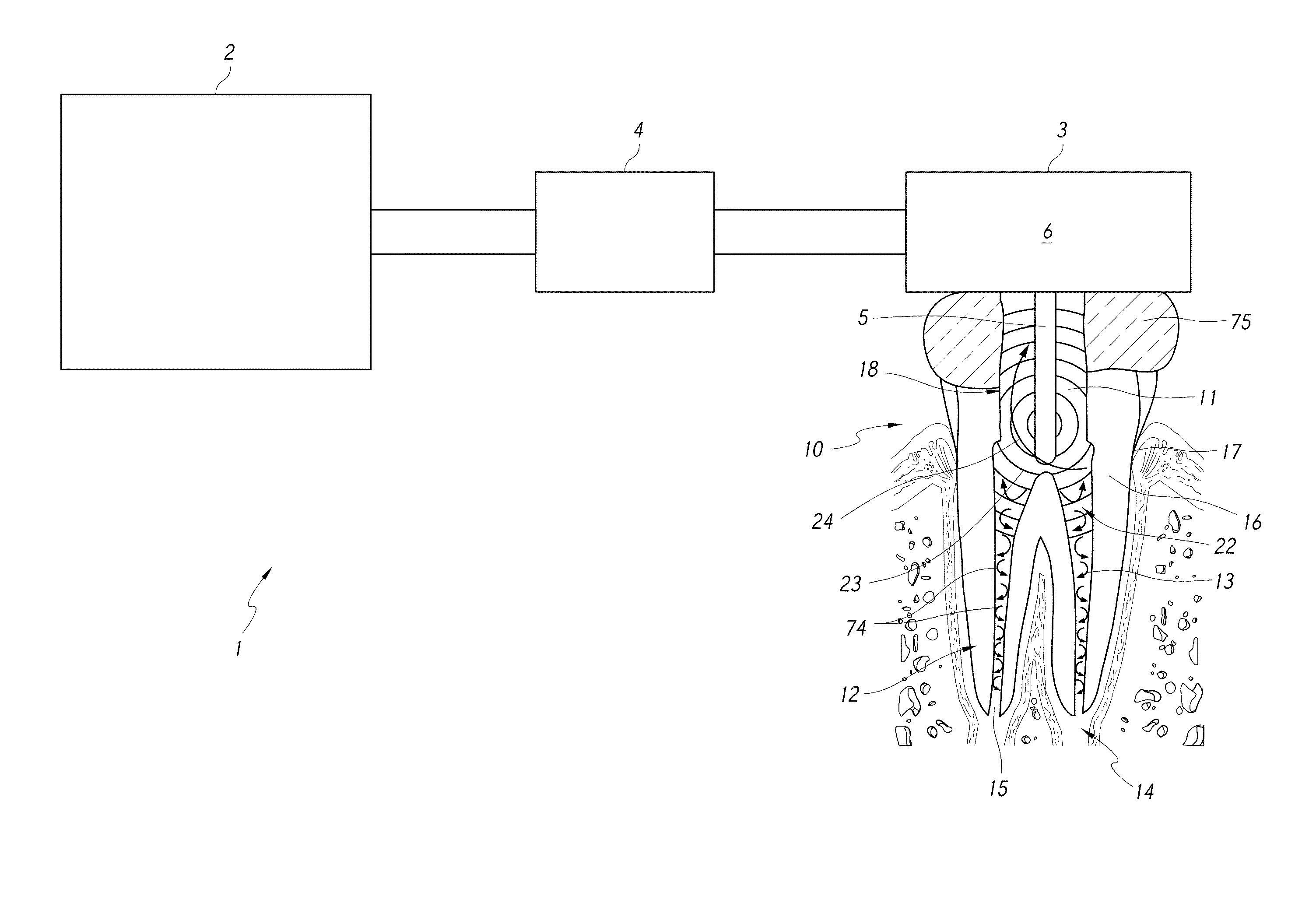
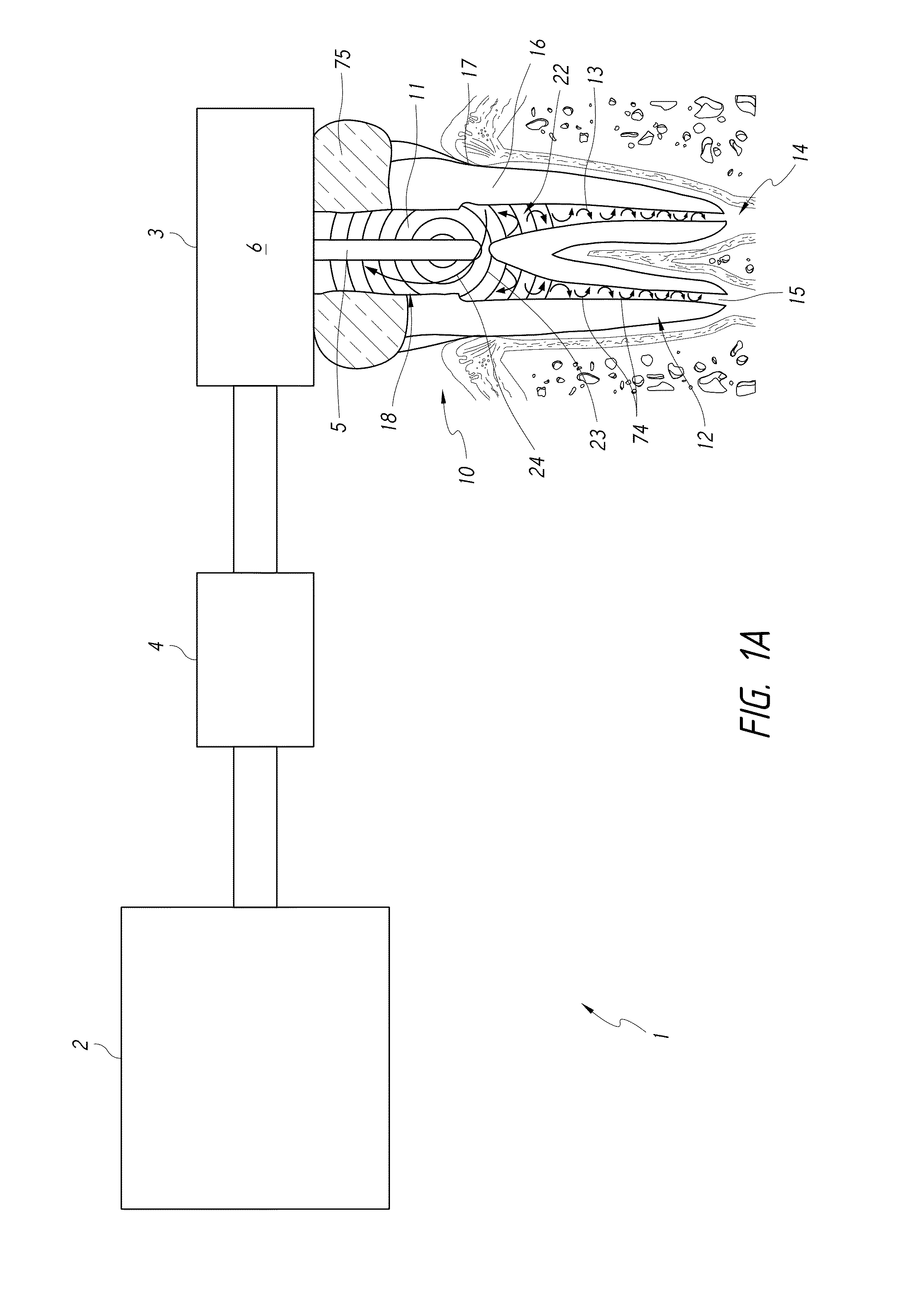
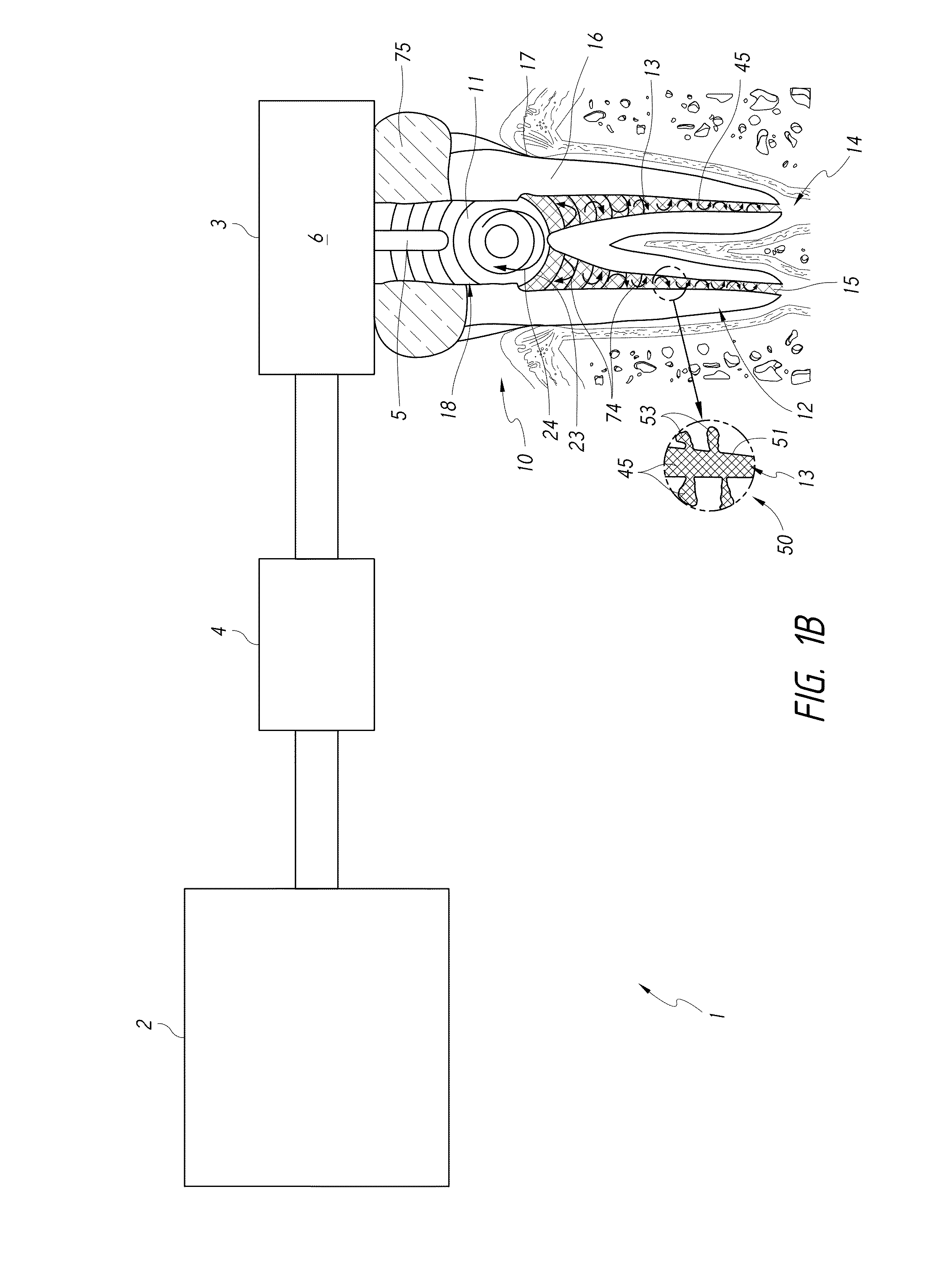
[0041]FIG. 1A is a schematic diagram of a system 1, in accordance with the embodiments disclosed herein. The system 1 shown in FIG. 1A may be configured to perform various types of treatment procedures, including, e.g., cleaning treatments, obturation treatments, restoration treatments, etc. In the embodiment shown in FIG. 1A, the system 1 is illustrated as being coupled to (e.g., positioned against in some arrangements) a tooth 10 that is a molar tooth of a mammal, such as a human. However, the tooth 10 may be any other suitable type of tooth, such as a pre-molar, bicuspid, incisor, canine, etc. Furthermore, the system 1 shown in FIG. 1A can include components configured to remove unhealthy or undesirable materials from a tooth or surrounding gum tissue, for example, a root canal 13 of the tooth 10. Thus, in the embodiment of FIG. 1A, the system 10 is configured to clean the tooth 10.

[0042]The tooth 10 include...


PUM


Abstract

A dental apparatus is disclosed. The dental apparatus can comprise a pressure wave generator to be disposed at a treatment region of a tooth. The pressure wave generator can include an opening to deliver a flowable filling material to the treatment region. The apparatus can include a reservoir for supplying the filling material to the pressure wave generator. The pressure wave generator can be configured to generate pressure waves through the treatment region to cause the filling material to substantially fill the treatment region.

Description

CROSS-REFERENCE TO RELATED APPLICATIONS[0001]This application claims the benefit of U.S. Provisional Patent Application No. 61 / 839,855, filed Jun. 26, 2013, entitled “APPARATUS AND METHODS FOR FILLING TEETH AND ROOT CANALS;” U.S. Provisional Patent Application No. 61 / 866,420, filed Aug. 15, 2013, entitled “APPARATUS AND METHODS FOR FILLING TEETH AND ROOT CANALS;” U.S. Provisional Patent Application No. 61 / 873,789, filed Sep. 4, 2013, entitled “APPARATUS AND METHODS FOR FILLING TEETH AND ROOT CANALS;” U.S. Provisional Patent Application No. 61 / 976,699, filed Apr. 8, 2014, entitled “APPARATUS AND METHODS FOR FILLING TEETH AND ROOT CANALS;” and U.S. Provisional Patent Application No. 61 / 982,223, filed Apr. 21, 2014, entitled “APPARATUS AND METHODS FOR FILLING TEETH AND ROOT CANALS,” each of which is hereby incorporated by reference herein in its entirety and for all purposes.BACKGROUND OF THE INVENTION[0002]1. Field of the Invention[0003]The present disclosure relates generally to dent...

Claims


Application Information

Patent Timeline
IPC IPC(8): A61C5/02A61C5/04A61C17/20A61C5/06A61C17/02
CPCA61C5/02A61C5/062A61C5/04A61C17/20A61C17/0202A61C17/028A61C1/087A61C5/50A61C5/62A61C5/40A61C17/024
Inventor KHAKPOUR, MEHRZADBERGHEIM, BJARNE
Owner SONENDO
Why Eureka
Try Eureka