
Rotary fertilizer applicator

a fertilizer applicator and rotary technology, applied in the field of agricultural fertilizer applicators, can solve the problems of limited gallons per acre of fertilizer application, and achieve the effects of wide range of application, reduced maximum gallons, and more concentration of nutrients

Active Publication Date: 2015-06-04
DIETRICH SR WILLIAM J
View PDF4 Cites 6 Cited by
  • Summary
  • Abstract
  • Description
  • Claims
  • Application Information

AI Technical Summary

Benefits of technology

The present invention is a device designed to work in different types of soil and heavy residue. It uses two conical shaped wavy blades to create openings side-by-side. The front coulter creates a slot and moves soil laterally, while the rear blade moves soil in the opposite direction. The loosened soil between the two paths is fractured to allow liquid to fill in the voids. The device can adjust its depth and can handle a wide range of soil moistures. The application rate can reach 2000 gallons per acre. The high gallon per acre sweep can accommodate a wide range of application rates.

Problems solved by technology

This coulter application has limitations regarding gallons per acre.

Method used


Image

  • Rotary fertilizer applicator
  • Rotary fertilizer applicator
  • Rotary fertilizer applicator

Examples


Embodiment Construction

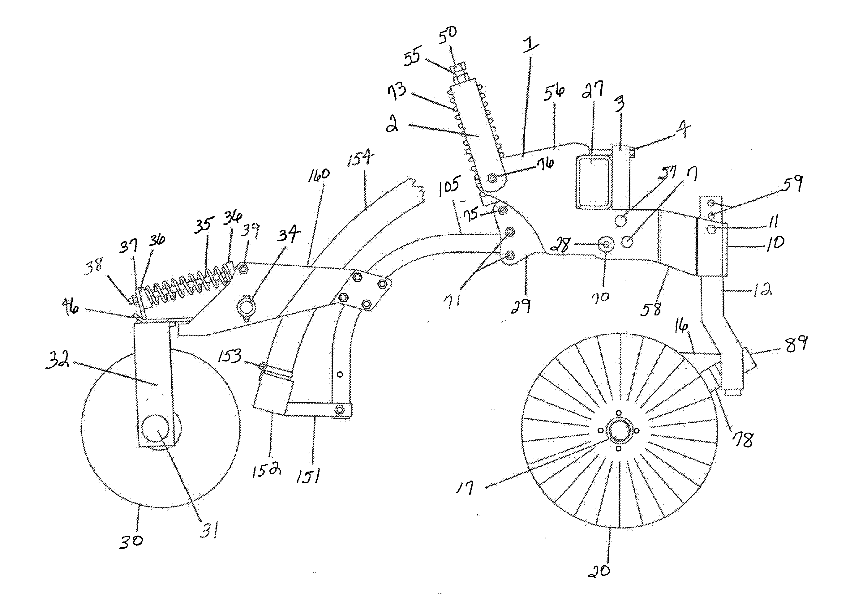
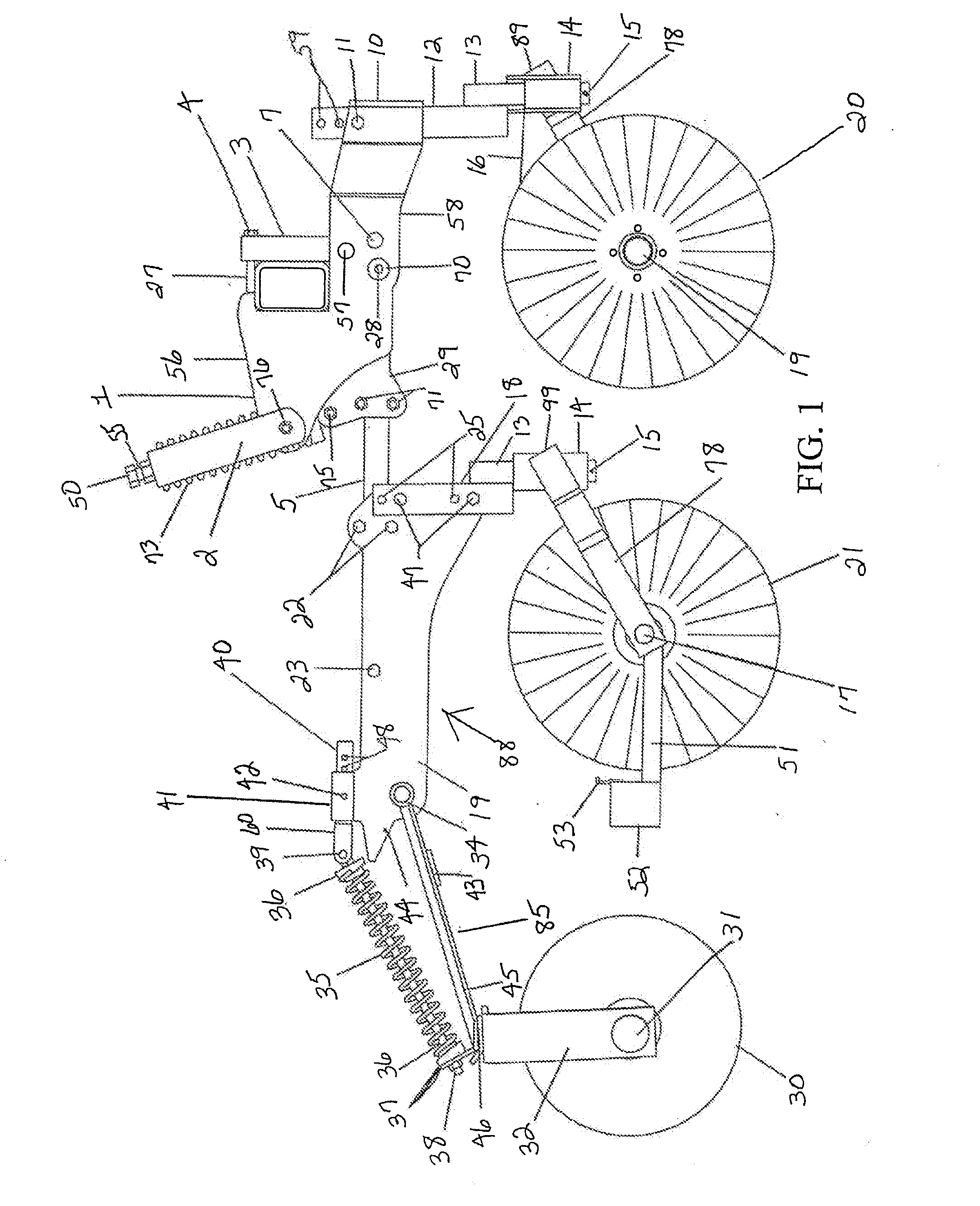
[0020]Referring to FIG. 1, there is shown a right side elevation view of the overall rotary applicator unit for spreading dry fertilizer or livestock waste in the form of a slurry. Reference number 1 generally designates a spring reset mechanism for a single row unit of a slurry applicator. As is known, a number of such applicator units are mounted on a wagon with a tool bar 27 drawn by a tractor (not shown). The applicator units are mounted in side-by-side relation and in a spaced manner. The tool bar 27, or frame, may have its own support wheels, or may be mounted to a wagon carrying the slurry. In any case, tool bar 27 trails a slurry wagon, or container, (also not shown for convenience) for a large amount of slurry fertilizer which is to be applied to a field. A coiled spring 73 is compressed (i.e. preloaded) and pivotally connected to a main shank 5 by bolt 55. When a rock or other obstruction is encountered by the rear conical coulter blade 21, the main shank 5, the rear conic...


PUM


Abstract

An applicator for applying dry fertilizer or livestock waste in the form of a slurry beneath the soil surface with minimum soil displacement includes a leading spring-cushioned, conical-shaped, wavy coulter angularly offset from the direction of travel which displaces soil laterally in forming a furrow adapted to receive fertilizer. The coulter is trailed by a single, or a pair of, rotary blade(s) which fill the furrow, covering the deposited fertilizer. A second embodiment includes a second wavy coulter disposed between the leading coulter and the trailing rotary blades for directing soil in a laterally opposed direction from the soil displaced by the leading coulter in forming a wider furrow. The single conical coulter and dual conical coulter embodiments are easily interchangeable in the applicator, and are easily removed and replaced with a curved shank and sweep assembly to convert to sweep fertilizer application.

Description

CROSS REFERENCE TO RELATED APPLICATION[0001]This application claims priority under 35 U.S.C. §119 from prior provisional application No. 61 / 609,037 which was filed on Mar. 9, 2012, herein incorporated by reference.FIELD OF THE INVENTION[0002]The present invention relates to agricultural fertilizer applicators; and more particularly, it relates to apparatus for subsoil application of dry fertilizer or livestock waste in the form of slurry (that is, a freely flowable mixture of liquids and solids).BACKGROUND OF THE INVENTION[0003]Historically, livestock waste, particularly in solid form, has been spread on the surface of the soil by a manure spreader using a flail to fling the material to the rear. A more modern side-discharge spreader also deposits the material on the surface of the soil.[0004]The advent of confinement systems for animals which include pits below the confinement area produces a large amount of animal waste in a slurry form which must be handled and disposed of. Typic...

Claims


Application Information

Patent Timeline
Patent Type & Authority Applications(United States)
IPC IPC(8): A01B49/06A01C23/02A01C21/00
CPCA01B49/06A01C23/023A01C21/002A01C23/025A01C5/064A01C23/022
Inventor DIETRICH, SR., WILLIAM J.
Owner DIETRICH SR WILLIAM J
Learn More