Virtual image display apparatus

a display apparatus and virtual image technology, applied in the field of virtual image display apparatus, can solve the problems of insufficient information amount, limited display screen size, and insufficient video viewing by observers, and achieve the effects of small size, light weight and abundant information

Active Publication Date: 2015-06-04
SEIKO EPSON CORP
View PDF2 Cites 28 Cited by
  • Summary
  • Abstract
  • Description
  • Claims
  • Application Information

AI Technical Summary

Benefits of technology

[0007]An advantage of some aspects of the invention is to provide a virtual image display apparatus which can display abundant information in a small size and a light weight.

Problems solved by technology

Meanwhile, as in a case of seeing the presented data while working on something else, the observer does not watch the video thoroughly.
However, the size of a display screen is limited by the request for the small size and the light weight, and there is a possibility that the information amount which can be displayed is not sufficient.
In this case, the entire apparatus becomes large, and it is difficult to design the apparatus.
In general, when the small size and the light weight are strongly required, the size of the display screen is limited, and the information amount which can be displayed according to this is limited.

Method used


Image

  • Virtual image display apparatus
  • Virtual image display apparatus
  • Virtual image display apparatus

Examples


example 1

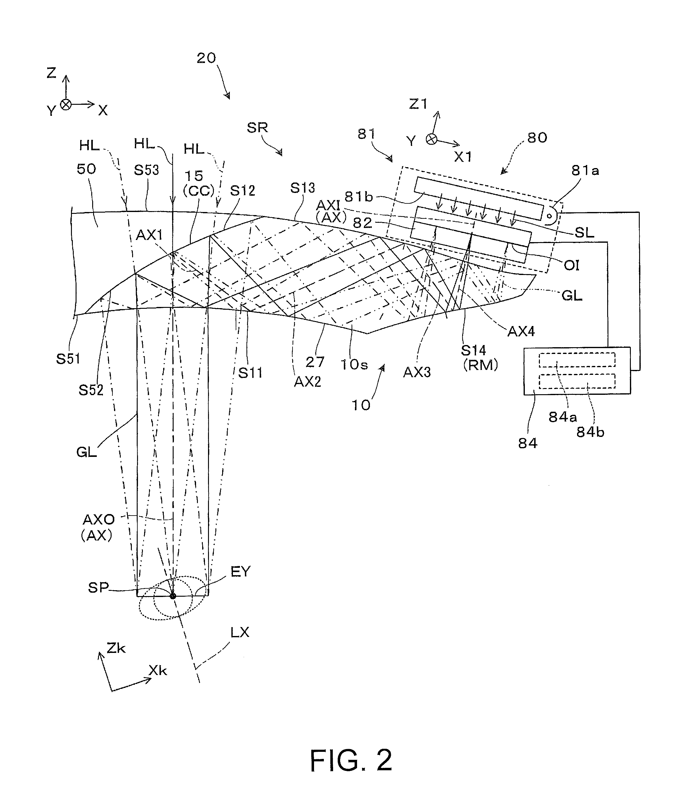
[0095]Data of the optical surface which constitutes the light guiding member of Example 1 is illustrated in Table 1 below. Here, the light ray which moves backward with respect to the forward movement of the video light from the position of the eyes is tracked and measured. The symbol FFSk (k=1 to 4) means the k-th surface among the first to the fourth surfaces S11 to S14 which are the free-form surfaces. In other words, FFS1 means the first surface S11, FFS2 means the second surface S12, FFS3 means the third surface S13, and FFS4 means the fourth surface S14. In addition, the symbol EP means the position of the pupil, that is, the position of the eyes EY. In addition, here, regarding each free-form surface which constitutes the light guiding member, by considering the symbol EP illustrating the position of the pupil as a reference position, that is, an absolute origin with respect to the entire position, a relative positional relationship with the origin of the local coordinates of...

example 2

[0099]Data of the optical surface which constitutes the light guiding member of Example 2 will be described in Table 3 below. The symbol FFSk (k=1 to 4) means the k-th surface among the first to the fourth surfaces S11 to S14 which are the free-form surfaces. In addition, as illustrated in FIGS. 8 and 9, in the embodiment, the light guiding member 10 has the third surface S13 and the fourth surface S14.

TABLE 3NoTypeXYZθNdVd1EP0.0000.0000.0000.002FFS10.0000.00020.0000.001.52555.953FFS20.0000.00024.00027.001.52555.954FFS10.0000.00020.0000.001.52555.955FFS314.9560.00025.981−9.061.52555.956FFS418.7270.00021.31438.948SPH22.1130.00017.12438.941.45867.829IMAGE22.8680.00016.19038.94

[0100]Regarding each optical surface in the light guiding member which constitutes the Example 2, the coefficient Akm,n which is polynomially expanded on the free-form surface is illustrated in Table 4 below. The coefficient Akm,n means the coefficient of each term xm·yn which constitutes the polynomial expressio...

second embodiment

[0102]Hereinafter, with reference to FIG. 12 or the like, the virtual image display apparatus according to the second embodiment of the invention will be described in detail.

[0103]A virtual image display apparatus 200 of the embodiment illustrated in FIG. 12 is employed in the head-mounted display (HMD), and includes the image display device 80 and a light guiding device 220 as one group.

[0104]The virtual image display apparatus 200 makes the image recognized by forming the virtual image by the image light to the observer, and makes the observer observe an external image in a see-through manner. The image display device 80 and the light guiding device 220 are generally provided at either of the right and the left eyes of the observer. However, a case where the apparatus is for the right eye is illustrated here, and the drawings and description of the virtual image display apparatus for the left eye will be omitted because the virtual image display apparatus for the left eye is merel...


PUM


Abstract

With respect to an emitting side optical axis, which is an optical axis on a first surface, a sight line reference axis which is assumed as a sight line axis of the eyes of an observer extends in a slightly inclined direction. In particular, the emitting side optical axis with respect to the sight line reference axis is configured to approach the eyes from the outside (that is, a corner of the eyes) of the eyes. In addition, a long image in a vertical direction which is perpendicular to an alignment of the eyes rather than in the horizontal direction which corresponds to the alignment of the eyes, is displayed.

Description

BACKGROUND[0001]1. Technical Field[0002]The present invention relates to a virtual image display apparatus which presents a video formed by an image display element or the like to an observer, and particularly relates to a virtual image display apparatus which is appropriate to a head-mounted display which is mounted on the head of the observer.[0003]2. Related Art[0004]Various technologies have been suggested as an optical system which is embedded in a virtual image display apparatus, such as a head-mounted display (hereinafter, referred to as an HMD), which is mounted on the head of an observer (refer to US Patent Application No. 2013-0033756, JP-A-7-333551, JP-A-9-73043, JP-A-2012-58302, JP-A-2005-17775).[0005]In the HMD in the related art, as an apparatus which presents a video to both eyes, a type which blocks external light or a see-trough type which presents a video by using a half mirror as a transparent member and overlapping the external light and video light, is employed ...

Claims


Application Information

Patent Timeline
Patent Type & Authority Applications(United States)
IPC IPC(8): G02B27/01F21V8/00
CPCG02B27/0172G02B2027/0178G02B6/0035G02B2027/015
Inventor KOMATSU, AKIRATOTANI, TAKAHIROTAKAGI, MASAYUKITAKEDA, TAKASHIMIYAO, TOSHIAKI
Owner SEIKO EPSON CORP
Why Eureka
Try Eureka