

Dual-optical-frequency-comb linear spectral encoding imaging method
A dual optical frequency comb and optical frequency comb technology, applied in the field of ultrafast optics, can solve problems such as difficult to achieve rapid image measurement and rapid extraction of various information, and achieve the effects of easy system installation and deployment, simple detection, and improved imaging speed
- Summary
- Abstract
- Description
- Claims
- Application Information
AI Technical Summary
Problems solved by technology
Method used
Image

Examples
Embodiment 1
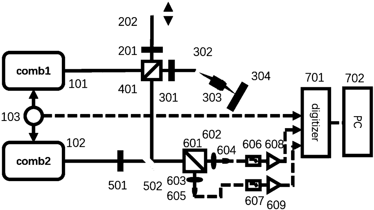
[0039] refer to figure 2 , the repetition frequency of the optical frequency comb 101 of the signal light source and the optical frequency comb 102 of the local oscillator light source are simultaneously locked with the external atomic clock 103; the signal light generated by the optical frequency comb 101 is divided into a reference light and a probe light by a polarization beam splitter 401; the reference light passes through The quarter-wave plate 201 and the mirror 201 pass through the quarter-wave plate 201 again, pass through the polarization beam splitter 401 and combine with the probe light. The probe light enters the spectrally encoded imager through the quarter-wave plate 301 . The spectrally encoded imager consists of a transmission grating 302 and a microscope objective lens 303 . The spectrum is spatially expanded by the transmission grating 302 and focused on the sample 304 to be measured through the microscope objective lens 303 . The reflected light containi...
Embodiment 2
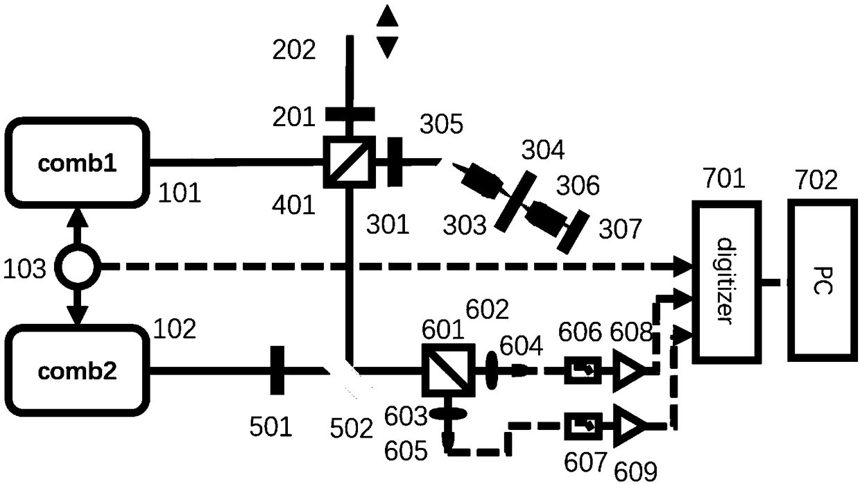
[0045] refer to image 3 , the repetition frequency of the optical frequency comb 101 of the signal light source and the optical frequency comb 102 of the local oscillator light source are simultaneously locked with the external atomic clock 103; the signal light generated by the optical frequency comb 101 is divided into a reference light and a probe light by a polarization beam splitter 401; the reference light passes through The quarter-wave plate 201 and the mirror 201 pass through the quarter-wave plate 201 again, pass through the polarization beam splitter 401 and combine with the probe light. The probe light enters the spectrally encoded imager through the quarter-wave plate 301 . The spectrally encoded imager consists of a prism 305 and a microscope objective 303 . The spectrum is spatially expanded by the prism 305 and focused on the sample 304 to be measured through the microscope objective lens 303 . The light transmitted through the sample to be measured passes t...
Embodiment 3
[0051] refer to Figure 4 The repetition frequency of the signal light source optical frequency comb 101 and the local oscillator light source optical frequency comb 102 is simultaneously locked with the external atomic clock 103; the signal light of the optical frequency comb 101 and the local oscillator light of the optical frequency comb 102 are simultaneously injected into the beam combiner 502. After passing through the beam combiner 502 , it is divided into a probe light and a reference light, and the two light beams include the signal light of the optical frequency comb 101 and the local oscillator light of the optical frequency comb 102 at the same time. The reference light passes through the compensation fiber, so that the optical path of the reference light is nearly equal to the optical path of the detection light. The reference light enters the photodetector 605 directly. The probe light passes through the fiber optic loop mirror 308 and the collimator 309 to perf...
PUM
 Abstract
Description
Claims
Application Information