Photovoltaic monolithic solar module connection and fabrication methods

a solar module and monolithic technology, applied in the field of photovoltaic (pv) solar cells, can solve the problems of power loss and reliability degradation, performance degradation, photovoltaic modules, etc., and achieve the effects of reducing disadvantages and deficiencies, reducing fabrication complexity, and increasing solar cell array performan

Inactive Publication Date: 2015-06-04
BEAMREACH SOLAR INC
View PDF5 Cites 17 Cited by
  • Summary
  • Abstract
  • Description
  • Claims
  • Application Information

AI Technical Summary

Benefits of technology

[0009]Therefore, a need has arisen for photovoltaic solar cell array solutions that decrease fabrication complexity and provide increased solar cell array performance. In accordance with the disclosed subject matter, photovoltaic solar cell arrays and fabrication methods are provided which substantially eliminates or reduces disadvantages and deficiencies associated with previously photovoltaic solar cell arrays and fabrication methods.

Problems solved by technology

Solar cells in current photovoltaic modules and array packages may be susceptible to cracks and breakage during module processing (e.g., module encaspulant lamination or tabbing / stringing for cell to cell interconnection) and subsequently during field installation and operation, resulting in power loss and reliability degradation.
In some instances, the soldering process and solder joints may result in some performance degradation due to thermal / mechanical stresses and may also result in field reliability failures due to solder joint and cell-to-cell ribbon interconnection failures.
Further, the costs of tabbing and stringing materials (e.g., Cu ribbon, solder), processes, and equipment may add to overall capital expenditures and manufacturing costs.
This spacing between the solar cells reduces the overall total-area module efficiency (due to the larger cell-to-module efficiency drop).
Often, there is an increased risk of cell breakage during and after module fabrication, resulting in reduced manufacturing yield and increased PV module manufacturing cost.

Method used


Image

  • Photovoltaic monolithic solar module connection and fabrication methods
  • Photovoltaic monolithic solar module connection and fabrication methods
  • Photovoltaic monolithic solar module connection and fabrication methods

Examples


Embodiment Construction

[0030]The following description is not to be taken in a limiting sense, but is made for the purpose of describing the general principles of the present disclosure. The scope of the present disclosure should be determined with reference to the claims. Exemplary embodiments of the present disclosure are illustrated in the drawings, like numbers being used to refer to like and corresponding parts of the various drawings. The dimensions of drawings provided are not shown to scale.

[0031]And although the present disclosure is described with reference to specific embodiments and components, such as a back contact back junction solar cell, one skilled in the art could apply the principles discussed herein to other solar cell structures (such as front contact or emitter wrap through—EWT-solar cells), fabrication processes (such as various metallization methods and materials, for example plating), as well as continuous backplane materials and formation, for example a dielectric material depos...


PUM


Abstract

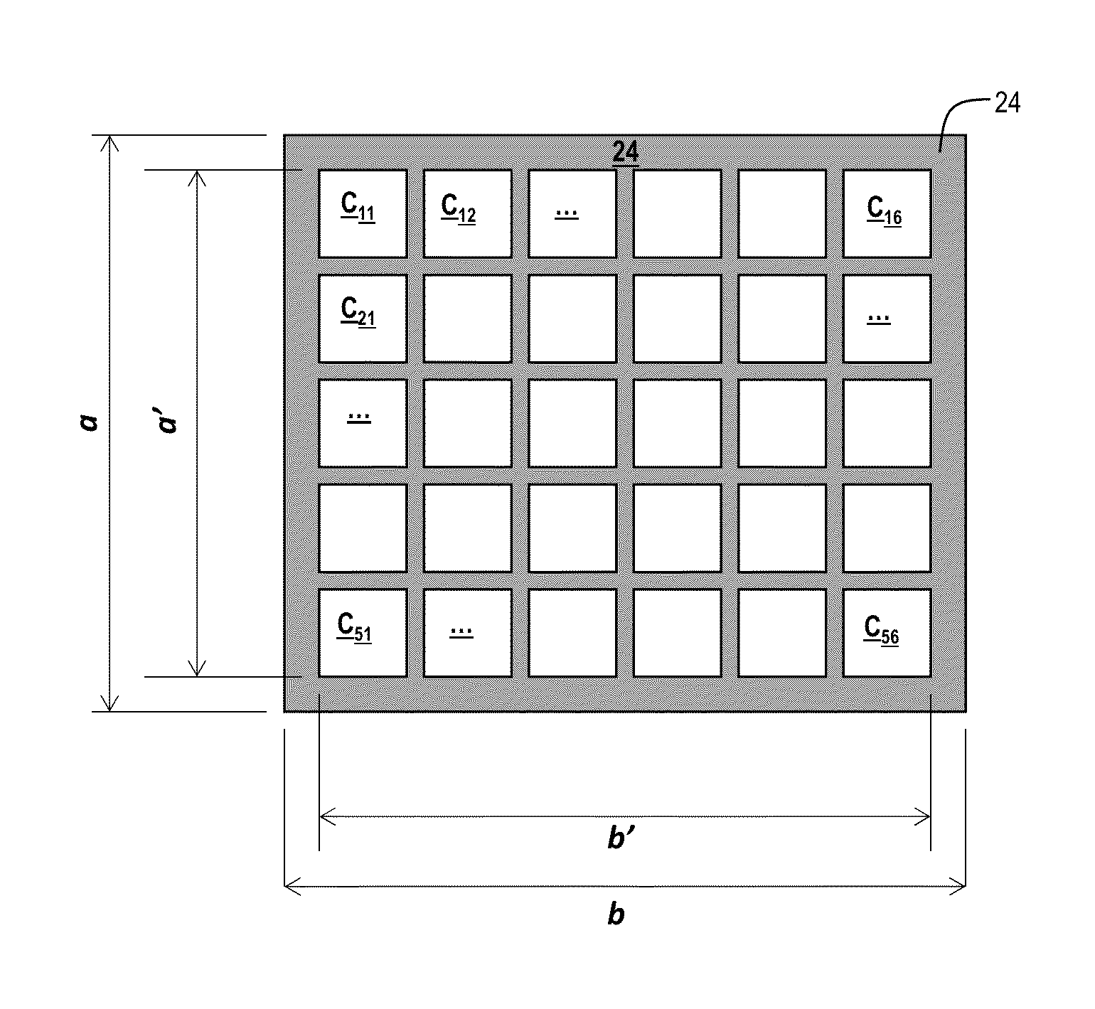
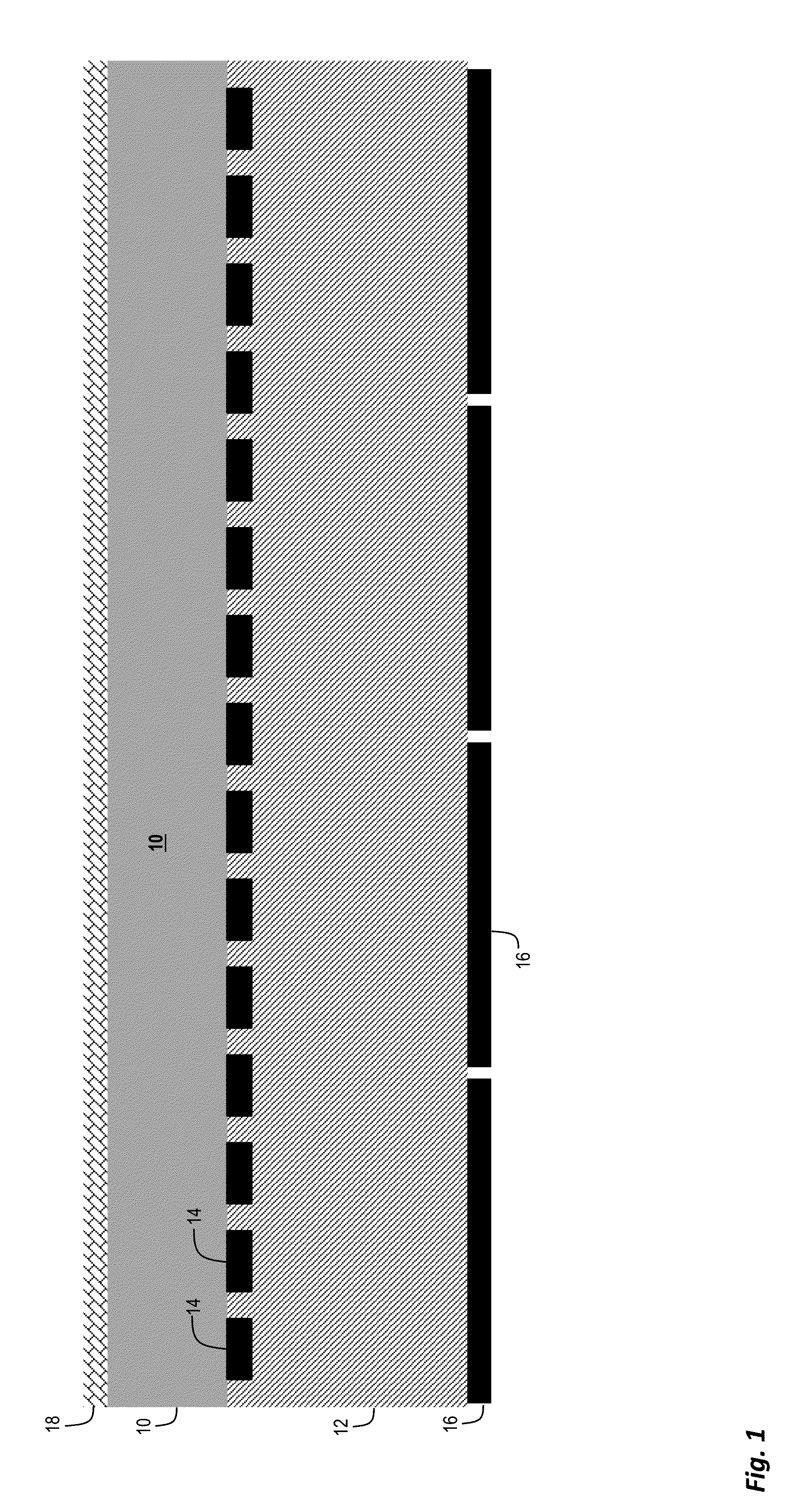
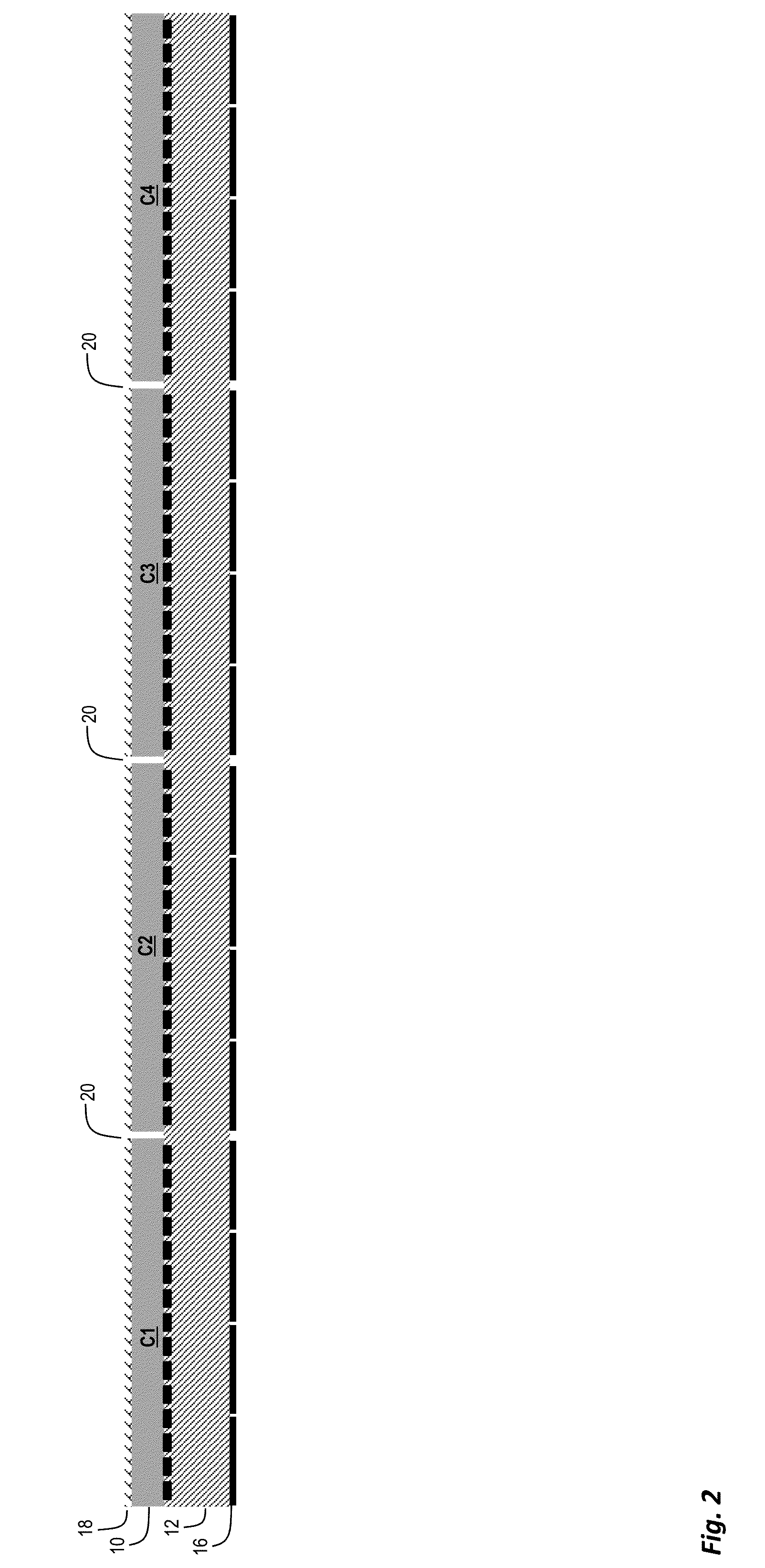
Solar cell array solutions including monolithic solar cell arrays and fabrication methods. A first patterned cell metallization contacts base and emitter regions of each of a plurality of solar cells having a light receiving frontside and a backside. An electrically insulating continuous backplane layer is attached to the backside of the solar cells and covers the first cell metallization of each of the solar cells. Via holes through the continuous backplane layer provide access to the first cell metallization. A second cell metallization is connected to the first cell metallization of each of the solar cells and electrically interconnects the solar cells in the array.

Description

CROSS-REFERENCE TO RELATED APPLICATIONS[0001]This application claims the benefit of U.S. provisional patent application 61 / 881,594 filed on Sep. 24, 2013, which is hereby incorporated by reference in its entirety.[0002]This application in a continuation in part of U.S. patent application Ser. No. 14 / 475,566 filed Sep. 2, 2014 which claims the benefit of U.S. provisional patent application 61 / 872,035 filed on Aug. 30, 2013, both of which are hereby incorporated by reference in their entirety.FIELD OF THE INVENTION[0003]The present disclosure relates in general to the fields of photovoltaic (PV) solar cells, and more particularly solar cell modules and module connections.BACKGROUND[0004]As photovoltaic solar cell technology is adopted as an energy generation solution on an increasingly widespread scale, fabrication and efficiency improvements relating to solar cell and module efficiency, metallization, mechanical support, and fabrication are required. Manufacturing cost and conversion...

Claims


Application Information

Patent Timeline
Patent Type & Authority Applications(United States)
IPC IPC(8): H01L31/0224H01L31/18H01L31/02H02S40/36
CPCH01L31/02245H01L31/02008H01L31/1868H02S40/36H01L31/0201H01L31/022441H01L31/0516Y02E10/50
Inventor MOSLEHI, MEHRDAD M.KRAMER, KARL-JOSEFKAPUR, PAWANSTALCUP, THOMWINGERT, MICHAEL
Owner BEAMREACH SOLAR INC
Why Eureka
Try Eureka