
Fluorescent LED lighting device and lighting on/off mode switching method therefor

Inactive Publication Date: 2015-06-04
NOGUCHI HINOKI
View PDF1 Cites 18 Cited by
  • Summary
  • Abstract
  • Description
  • Claims
  • Application Information

AI Technical Summary

Benefits of technology

The present invention provides an LED lighting system that can automatically determine the appropriate mode among normal lighting mode, normal light-out mode, and emergency lighting mode and control the LED lights accordingly. This system can lighten up LED lights in an emergency situation, such as a power failure or fire, and can also be used in normal situations to control the LED lights. The system can detect the electric flow condition even after all the people have left the room, ensuring safety and comfort. The user can select the desired lighting mode based on their needs. Overall, this LED lighting system provides a flexible and efficient solution for lighting up LED lights in various situations.

Problems solved by technology

However, they are not lightened in an emergency such as a power supply shutdown.
However, the conventional emergency lights have been installed individually from the normal illumination devices, which should in practice limit the number and place of the emergency lights to be installed.
Therefore, all of the nearby people would rush toward the place of installment of the emergency lights, which could result in an expected accident.

Method used


Image

  • Fluorescent LED lighting device and lighting on/off mode switching method therefor
  • Fluorescent LED lighting device and lighting on/off mode switching method therefor
  • Fluorescent LED lighting device and lighting on/off mode switching method therefor

Examples


embodiment 1

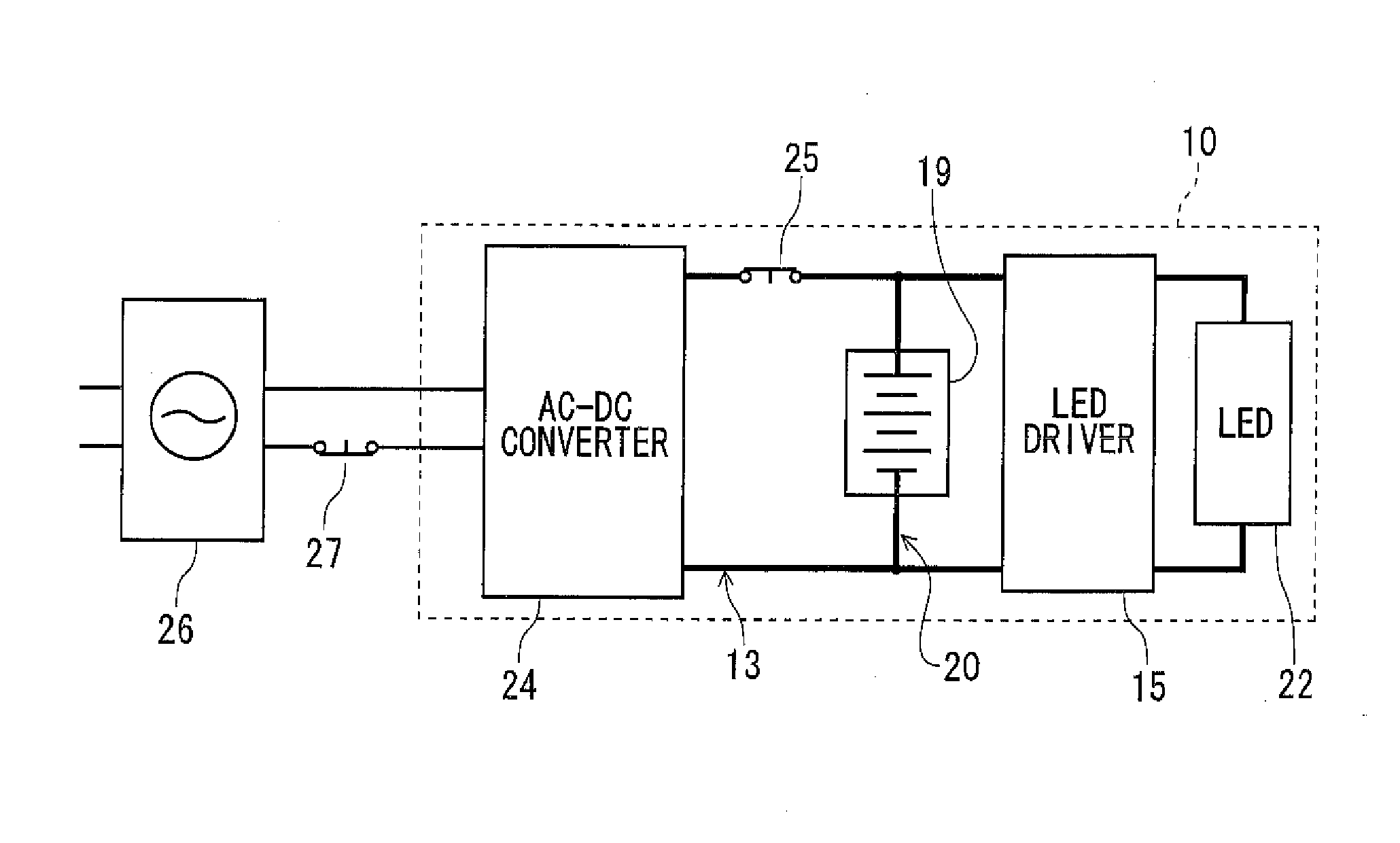
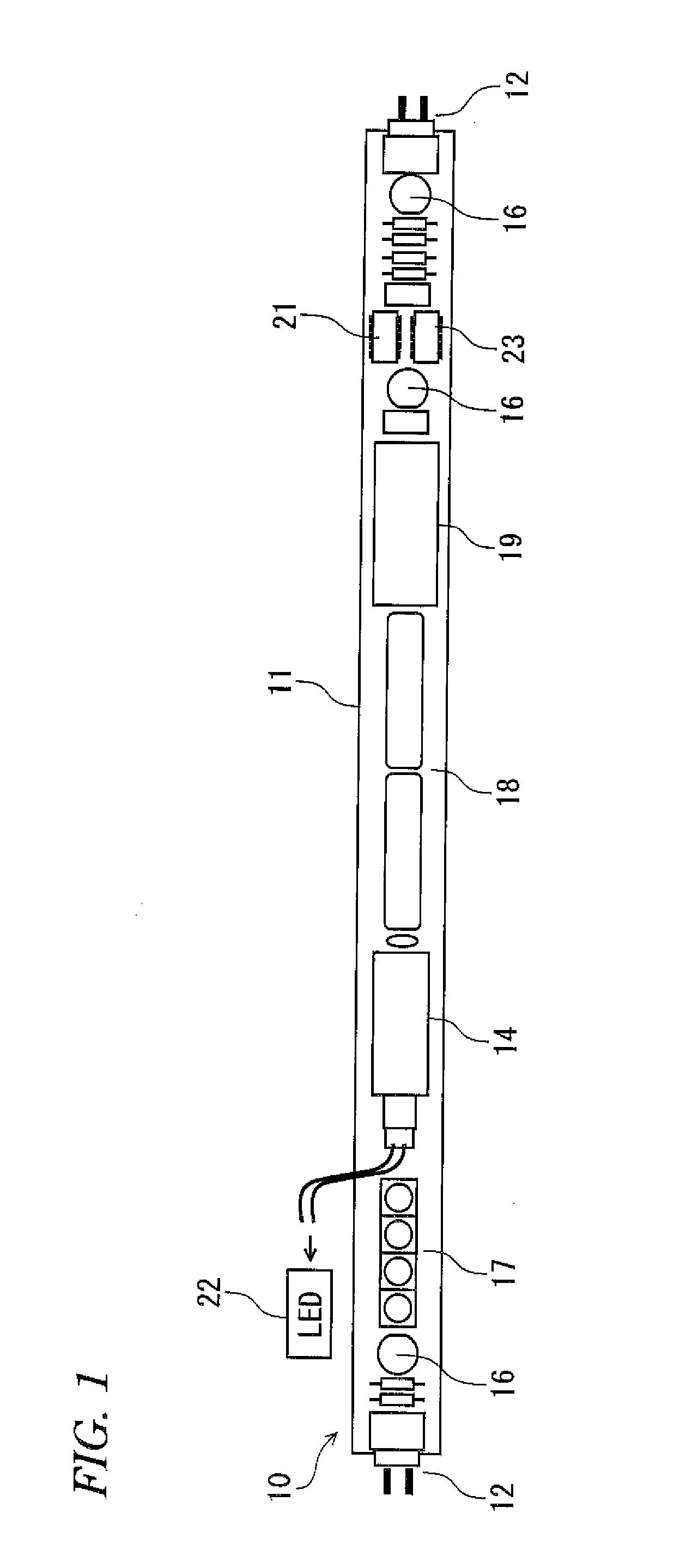
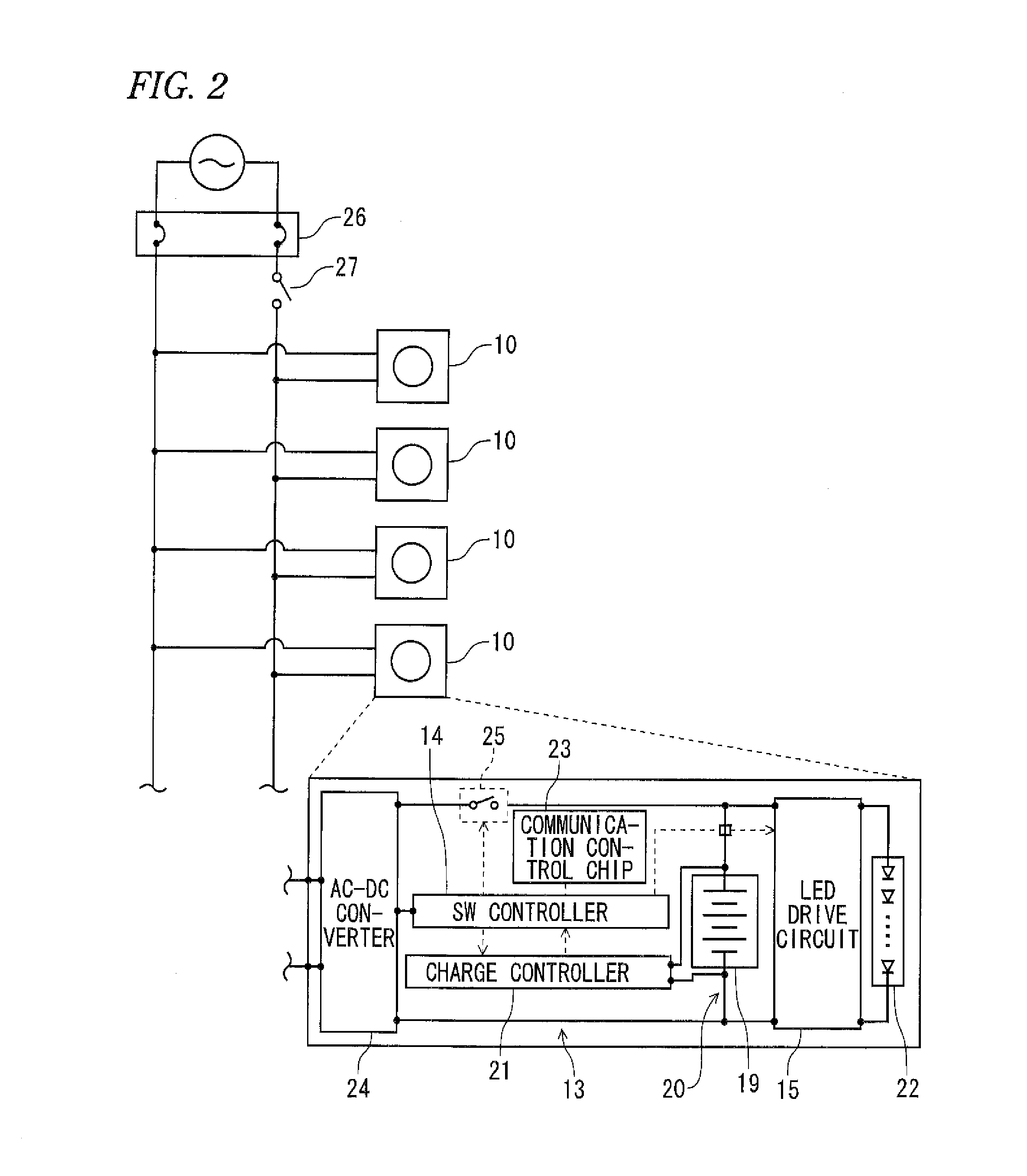
[0029]In reference to FIG. 1 and FIG. 2, an LED illumination device 10 is usable in substitution of the existing fluorescent lamp, which has the same size and shape as those of the existing fluorescent lamp and may be fitted between a pair of sockets already installed for the existing fluorescent lamp. The LED illumination device 10 has a cover 11 of substantially a cylindrical cross-section, in which an LED mount base (not shown) for mounting LED's thereon is securely contained. The light emitting from the LED's is transmitted through or diffused by the cover 11 for illumination. In one embodiment, the cover 11 is divided into two substantially half-around parts, one comprising a cover member made of plastic material having light transparency, light semi-transparency or light diffusion property, such as polycarbonate, and the other comprising a heat sink made of heat radiation property, such as aluminum. The LED mount base or substrate is contained in the cover member, and power su...

embodiment 2

[0049]In accordance with Embodiment 1 described above, when the sequential ON / OFF operation based on the prescribed manner is completed within a predetermined time interval, the switch controller 14 discriminates such that the normal intentional light-out operation has been carried out (S107:No) and turns off all the LED illumination devices 10 in the room (S111). If a power supply shutdown should happen in this state, the LED illumination devices 10 cannot be lightened as the emergency lights. Accordingly, when workers are going to enter the room for the purpose of doing the restoration works to recover the power supply, they might feel inconvenience and could not work in a safe working environment. In addition, when any stuff who does not know the power supply shutdown is going to enter the room, he or she may also feel something wrong or strange. Another embodiment designed to avoid such disadvantages will now be described in reference to FIG. 7 and FIG. 8.

[0050]FIG. 7 is a flowc...

embodiment 3

[0054]Although Embodiment 1 and Embodiment 2 have been described separately, they may be combined with each other to formulate another embodiment. More specifically, when considering safety and convenience, it is preferable to provide the power detection mode applicable to the normal light-out operation, but it would be desirous in some cases that, even when a power supply is cut off in absence, the LED illumination device 10 should not be lightened as the emergency light but may be kept turned off, depending upon a building or room in which the device is installed. To cope with such requirement, there may be an embodiment wherein, when the sequential OFF→ON operation of the external switch 27, formerly being ON, has been carried out within a predetermined time interval T, as in the same way as in Embodiment 2, the system goes to the power detection mode so that it keeps the normal light-out (S113), as far as the electricity is alive (S112:Yes), but is ready to goes to the emergency...


PUM


Abstract

In order to add an emergency light function to a fluorescent LED lighting device, thereby increasing safety during a power outage, this LED lighting device, which can be mounted between a pair of sockets for fluorescent lighting, is equipped with a first power supply circuit, which lights the LED using direct current power obtained by converting / rectifying alternating current power supplied from the sockets, and a second power supply circuit, which lights the LED using an embedded battery. An embedded SW controller detects that a sudden drop in the current value or the voltage value in the lighting device, from a prescribed value Von when the lighting switch is turned on to a value that is essentially zero, occurs within a prescribed time T. When the sudden drop occurs two or more times in the prescribed time (FIG. 5), it is determined that a normal operation of turning off the light has been performed, and the light is turned off, and when the sudden drop occurs only once during the prescribed time (FIG. 6), it is determined that a power outage has occurred, and the LED is lighted as an emergency light using the second power supply circuit.

Description

FIELD OF INVENTION[0001]The present invention relates to an illumination device using a LED (light emitting diode) light source, which is usable in substitution of an existing fluorescent lamp, and a lighting ON / OFF mode switching method therefor.BACKGROUND ART[0002]Fluorescent lamps have been frequently used as indoor and outdoor illumination devices. However, they are not lightened in an emergency such as a power supply shutdown. Accordingly, the Building Standards Act of Japan requires that there should be installed emergency lights in commercial facilities and accommodations for the purpose of providing a sufficient degree of illumination to an escape route for evacuation.[0003]However, the conventional emergency lights have been installed individually from the normal illumination devices, which should in practice limit the number and place of the emergency lights to be installed. This means that, in an emergency, only a small number of the emergency lights are lightened in dark...

Claims


Application Information

Patent Timeline
IPC IPC(8): H02J9/02H05B33/08H05B44/00
CPCH02J9/02H05B33/0845H05B33/0806H02J9/06H02J9/065Y02B20/30H05B45/10H05B45/37H05B47/105H05B45/3578H05B47/17F21Y2115/10H05B45/00
Inventor NOGUCHI, HIROKAZU
Owner NOGUCHI HINOKI
Learn More