
Bone Plate

a bone plate and plate body technology, applied in the field of bone plates, can solve the problems of reducing the flexibility reducing the strength of the bone plate, so as to and reduce the risk of fractur

Active Publication Date: 2015-06-11
DEPUY SYNTHES PROD INC
View PDF7 Cites 13 Cited by
  • Summary
  • Abstract
  • Description
  • Claims
  • Application Information

AI Technical Summary

Benefits of technology

This patent is for a bone plate used in orthopedic surgery. The technical effects of the patent are through the provision of a cavity and a depression in the non-bone-facing second surface of the bone plate, which reduces stress in the region of the first through hole and avoids breakage in this region. The cavity and the depression border on each other and pass into each other, which simplifies the production of the cavity and the depression. The cavity is elongate in shape, spanning a greater region between the first through hole and the head portion. The recesses are grouped and associated with one of the through holes, which improves the distribution of bending load. The recesses do not extend over the total width of the bone plate to avoid excessive weakening. Overall, this patent provides a safer and stronger bone plate for orthopedic surgery.

Problems solved by technology

However, a bone plate attached to a bone is subject to mechanical loads, in particular a bending load.
In particular, an elongate bone-plate shaft portion that is provided with through holes along its length has an irregular moment-of-resistance curve along its length and, upon excessive load, will be most likely to break in the region of a through hole, or at least be deformed in the region of a through hole, which would impede the introduction of a bone anchor through the through hole.
For example, in a bone plate for the proximal femur comprising an elongate shaft portion and a head portion that is shorter and wider in comparison thereto, an especially high load occurs in the region of the through hole that is closest to the head portion, so that the risk of breakage is highest here.

Method used


Image

  • Bone Plate
  • Bone Plate
  • Bone Plate

Examples


Embodiment Construction

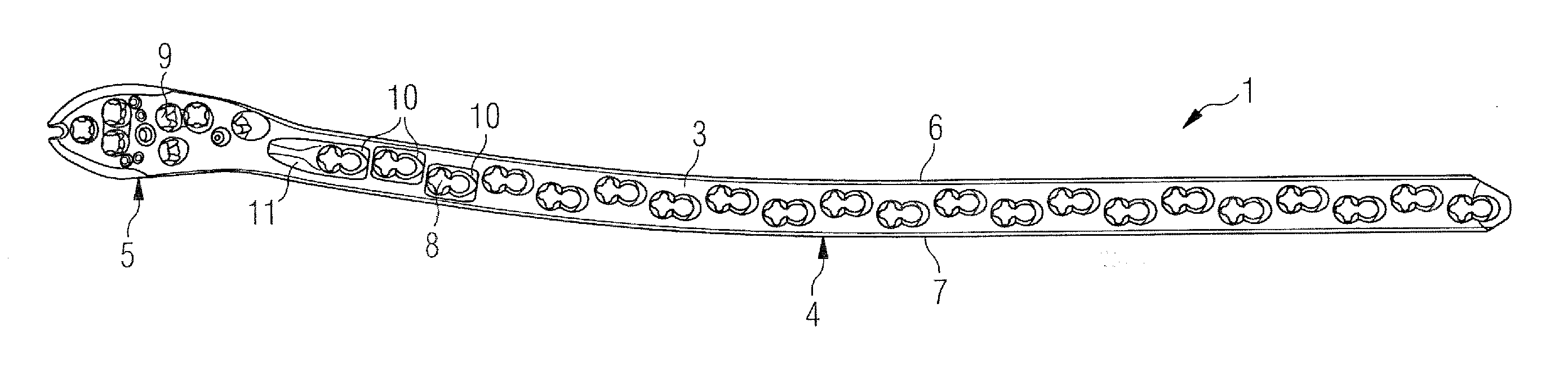
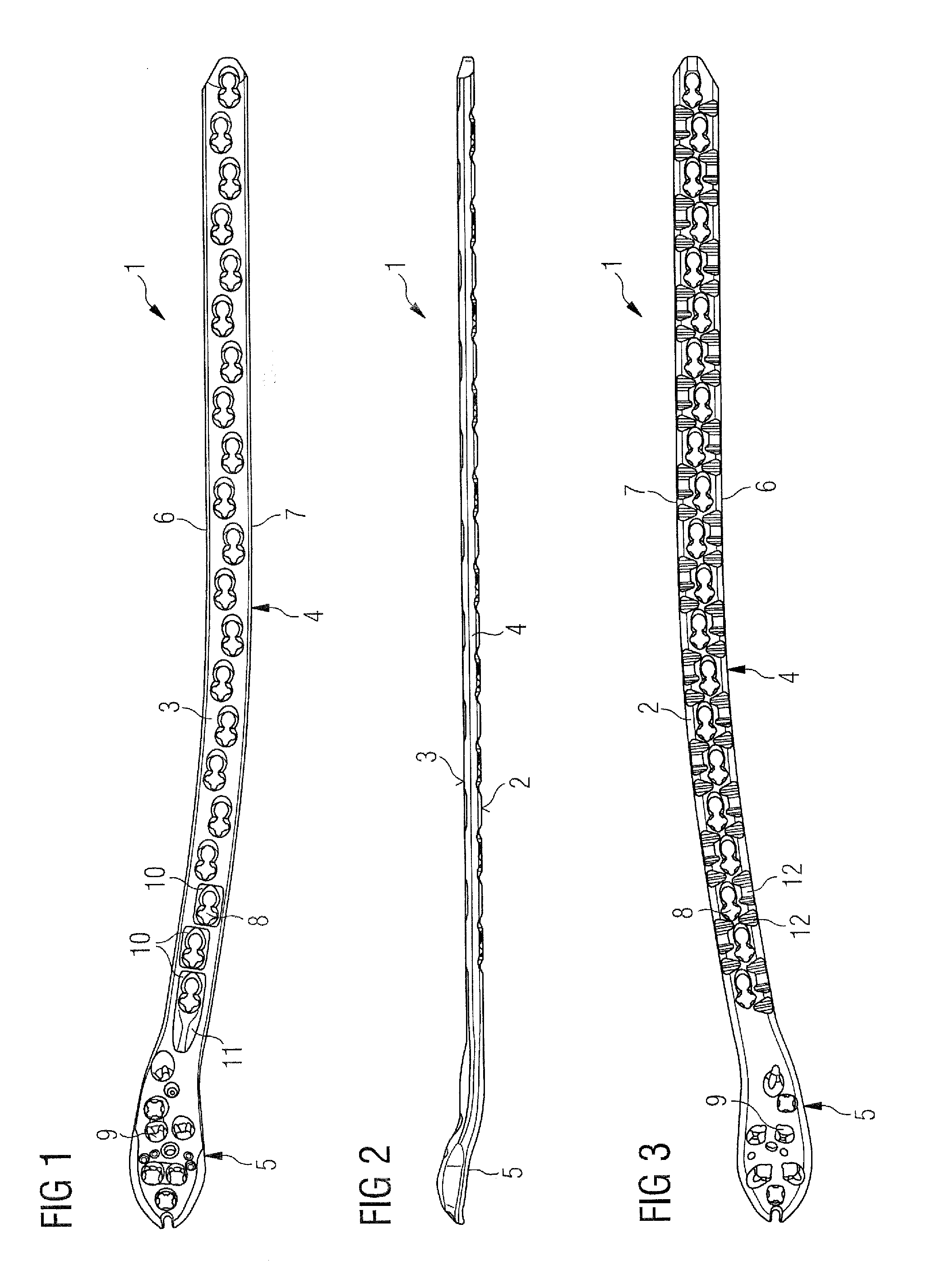
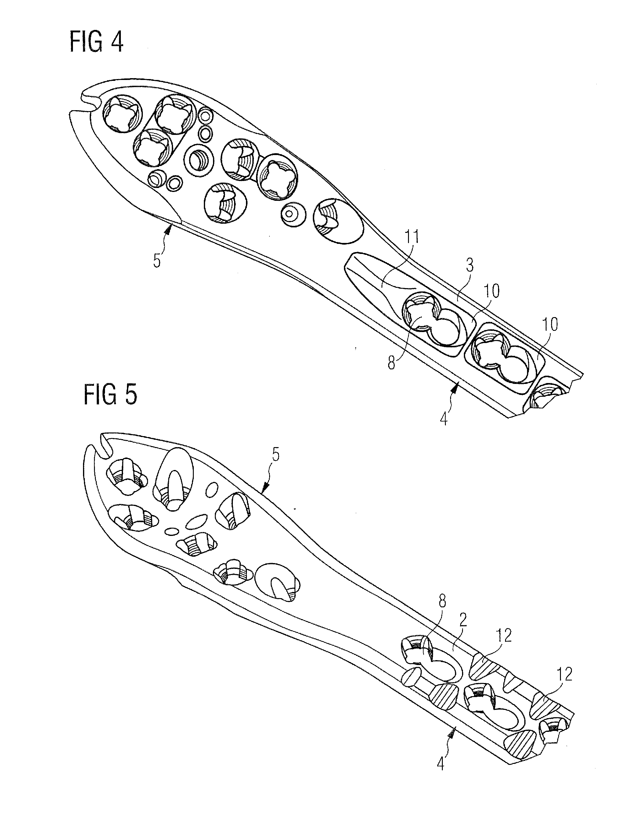
[0037]The present invention may be further understood with reference to the following description and the appended drawings, wherein like elements are referred to with the same reference numerals. Exemplary embodiments of the present invention describe a bone plate for fixing fractures. In particular, the exemplary embodiments describes a bone plate including a depression extending through the bone plate and surrounding a through hole extending therethrough to reduce stress peaks, for example, along a portion of the between a through hole and a lateral side wall of the bone plate. Although the exemplary embodiments specifically describe a bone plate configured for the fixation of a proximal femur, it will be understood by those of skill in the art that the bone plate of the present invention may be adapted for the fixation of any of a variety of bones and, in particular, load bearing long bones.

[0038]FIG. 1 shows an exemplary embodiment of a bone plate 1 in plan view from an upper s...


PUM


Abstract

A bone plate includes a first surface which, when the bone plate is positioned over a bone, faces the bone, and a second surface opposing the first surface, the bone plate comprising an elongate shaft portion extending along a longitudinal axis of the bone plate and including a plurality of through holes extending therethrough from the first surface to the second surface to receive a bone anchor therethrough and a head portion extending from an end of the elongate shaft portion along a length smaller than a length of the elongate shaft portion, a width of the head between lateral walls connecting edges of the first and second surface being greater than a width of the shaft distance between the lateral walls, wherein the second surface includes a cavity extending between a first one of the plurality of through holes situated closest to the head portion and the head portion.

Description

FIELD OF THE INVENTION[0001]The present invention relates to the field of surgical devices. Specifically, the invention relates to a bone plate for fixing bone segments, in particular, the proximal femur of a patient.BACKGROUND[0002]For stabilizing and fixing bone fractures it is known to employ bone plates which are fixed on the bone by means of suitable fastening elements such as, for example, bone screws, along with pins, bolts or other bone anchors. To guarantee a secure fixation of the bone fragments to each other and of the bone plate on the bone, it is required that the bone anchors are incorporated into the bone precisely and so as to be adapted to the anatomy.[0003]However, a bone plate attached to a bone is subject to mechanical loads, in particular a bending load. This load acts particularly on the weakest regions of a bone plate, namely those regions where through holes are provided. In particular, an elongate bone-plate shaft portion that is provided with through holes ...

Claims


Application Information

Patent Timeline
IPC IPC(8): A61B17/80
CPCA61B17/80A61B17/8057A61B17/8061
Inventor WOLF, STEFANAEBI, THIS
Owner DEPUY SYNTHES PROD INC
Learn More