

Vehicle braking/driving force control apparatus
- Summary
- Abstract
- Description
- Claims
- Application Information
AI Technical Summary
Benefits of technology
Problems solved by technology
Method used
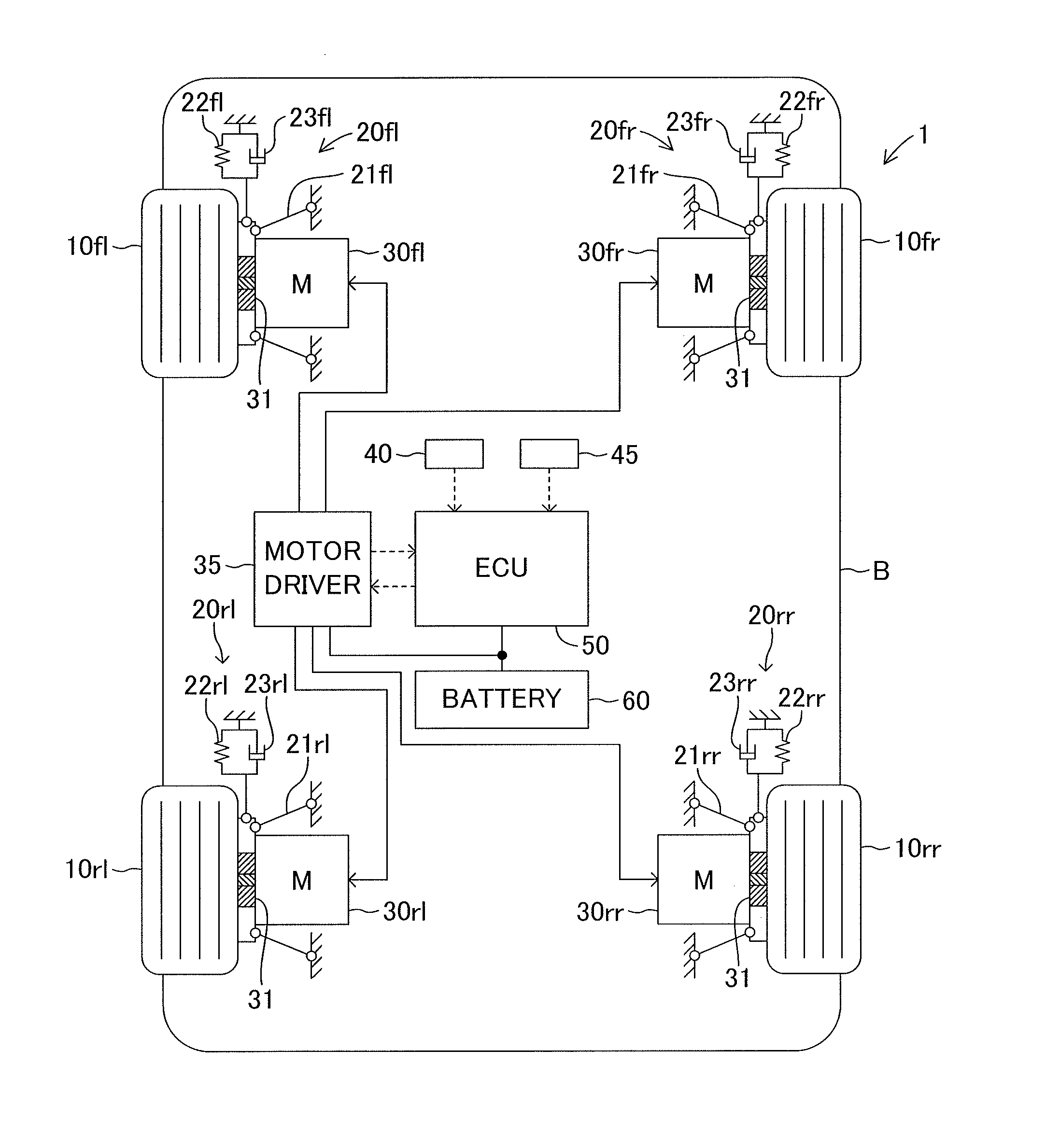
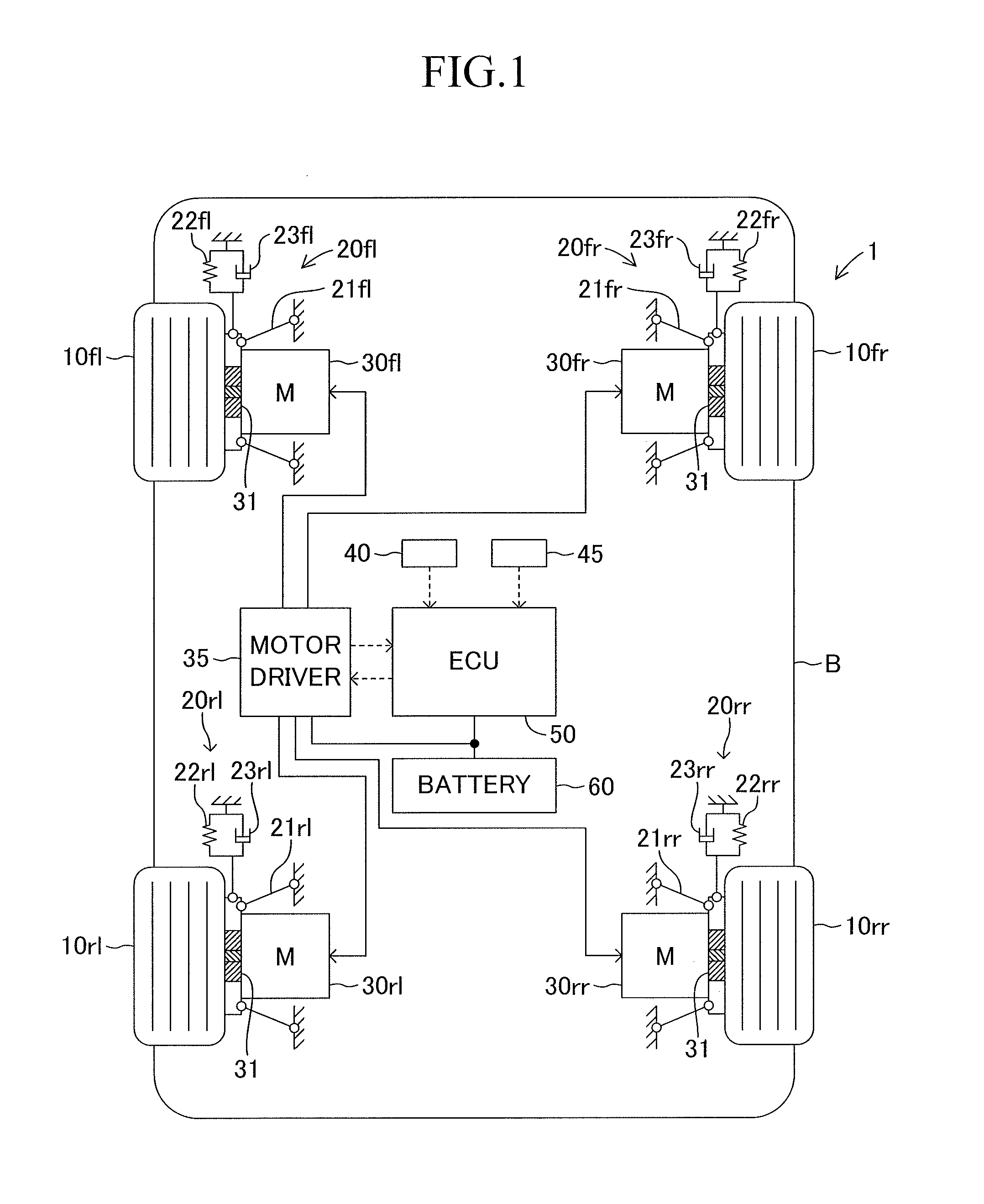
Image

Examples
second embodiment
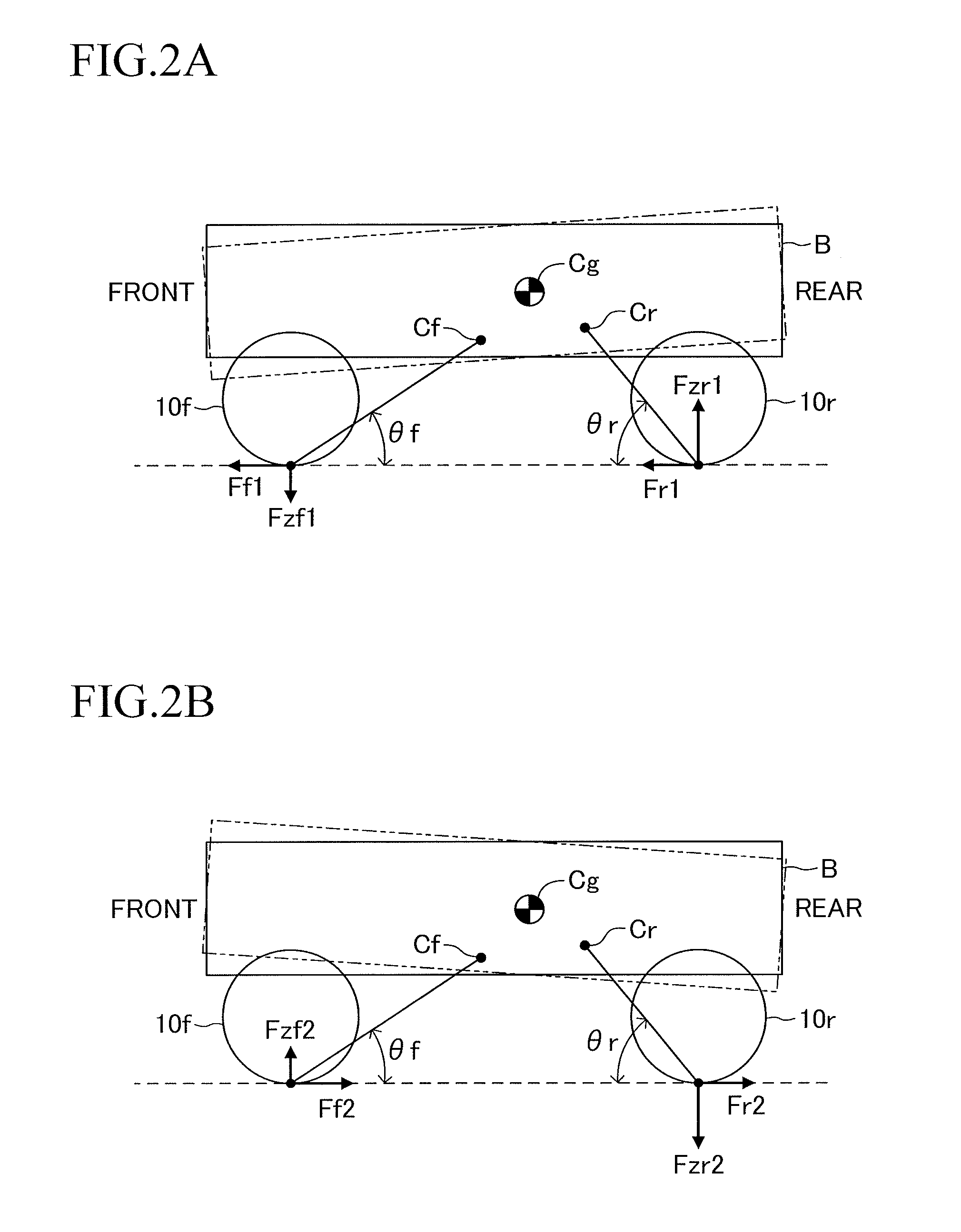
[0097]A description is now given of a second embodiment of the present invention. The embodiment described above is hereinafter referred to as first embodiment. In the first embodiment, the ratio of distribution of the driver-requested driving force Freq to the front / rear wheels 10f and 10r is set so that the margin to the zero cross of the motor torque is equal for the front and rear wheels 10f and 10r. In this case, the noise and the vibration caused by the backlash can be restrained from being generated, but the target braking / driving forces Ffl and Ffr on the front wheels 10f, which are the wheels on the side smaller in vertical force conversion rate, first reach the driving limit of the motors 30. In other words, reserve forces for generating the vertical forces on the front wheels 10f are lost earlier than on the rear wheels 10r. For example, as described above, when the roll control is carried out in order to balance the front-wheel-side roll moment and the rear-wheel-side ro...
PUM
 Abstract
Description
Claims
Application Information