Vessel with rotatable pod

a technology of displacement vessel and rotatable pod, which is applied in the direction of waterborne vessels, vessel construction, and propulsive elements, etc., can solve the problems of complicated movements and other problems, and achieve the effect of large draught and effective and efficien

Inactive Publication Date: 2015-06-11
BLUE THRUSTER
View PDF8 Cites 7 Cited by
  • Summary
  • Abstract
  • Description
  • Claims
  • Application Information

AI Technical Summary

Benefits of technology

[0014]As a result of the non-vertical placement of the second axis in combination with the non-perpendicular positioning of the first axis with respect to the second axis, in the case of rotation about the second axis the first axis will always be moved into a different position with respect to the horizontal (and the vertical) depending on the rotation. In the simplest embodiment, the first axis, i.e. the axis of the propeller shaft, defines a cone during rotation about the second axis, i.e. the axis of rotation of the pod. More complicated movements are also possible. This enables the position of the axis of the propeller shaft to be adjusted depending on the rotation position of the housing of the pod. In other words, in a drive position, or rearward position, said axis of the propeller shaft is preferably in the usual horizontal position. However, following rotation through 180° into the forward position of the pod, the axis of the propeller shaft will form a considerable angle with the horizontal. As a result of this tilting of the propeller shaft and thus of the propeller, the depth of the inlet of the annular jet pipe under the surface of the water increases with respect to the vertical, since it receives a horizontal component. The upper side of the peripheral edge of the jet pipe therefore lies deeper in the water in the forward position and is able to suck in this water, without a disruptive amount of air being sucked in during the process.
[0017]Surprisingly, it has been found that the jet pipe according to the invention which is arranged at an angle demonstrates a very good propulsive effect, even if the peripheral edge of the inlet is only slightly below the surface of the water. Air which flows in is pressed against the inner wall of the jet pipe by means of the centrifugal effect of the propeller, without the air bubbles which flow in entering the propeller and greatly reducing the efficiency of the propulsion.
[0020]By reversing the orientation and the direction of rotation of the pod in the case of a low degree of loading, the peripheral edge of the jet pipe is situated far enough below the surface of the water to realize effective propulsion. This enables sailing with a low draught without ballast.
[0031]In an embodiment in which the vessel is provided with at least two pod drives, at least one pod drive may be in the forward position, and the other in the rearward position. When sailing away at low speed, the propeller of the pod in the rearward position may not be driven and the pod in the forward position can provide the propulsion by means of water suction. If, after a predetermined speed has been reached, a sufficiently large stern wave has built up, the rotation of the propeller of the pod in the forward position may be ended and the pod in the rearward position may assume the propulsion. The second pod may then also be rotated into the rearward position in order to assist with the propulsion. This permits an efficient transfer of the propulsion from the pod in the forward position, without interruptions.

Problems solved by technology

More complicated movements are also possible.
However, this operation is temporary.

Method used


Image

  • Vessel with rotatable pod
  • Vessel with rotatable pod
  • Vessel with rotatable pod

Examples


Embodiment Construction

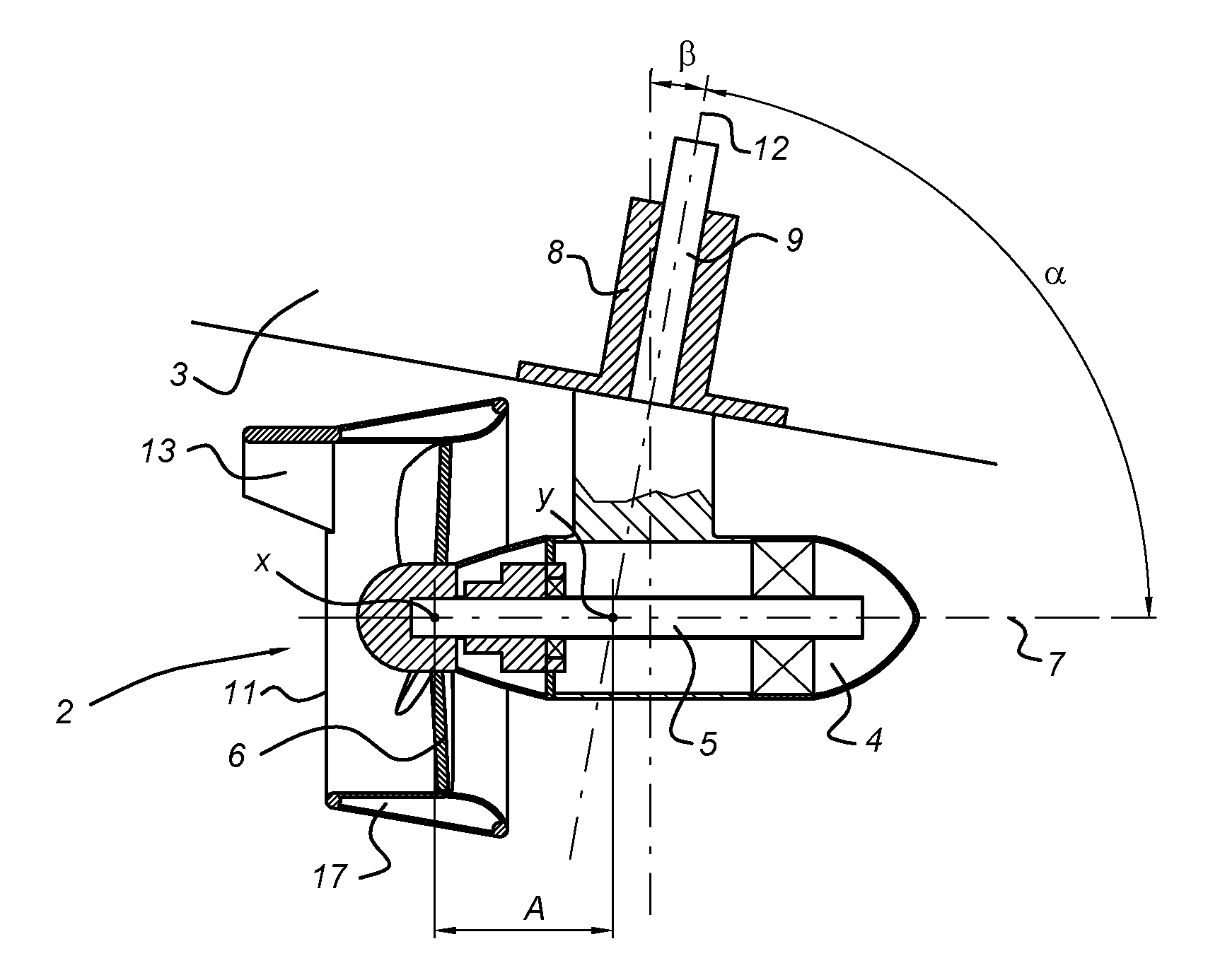
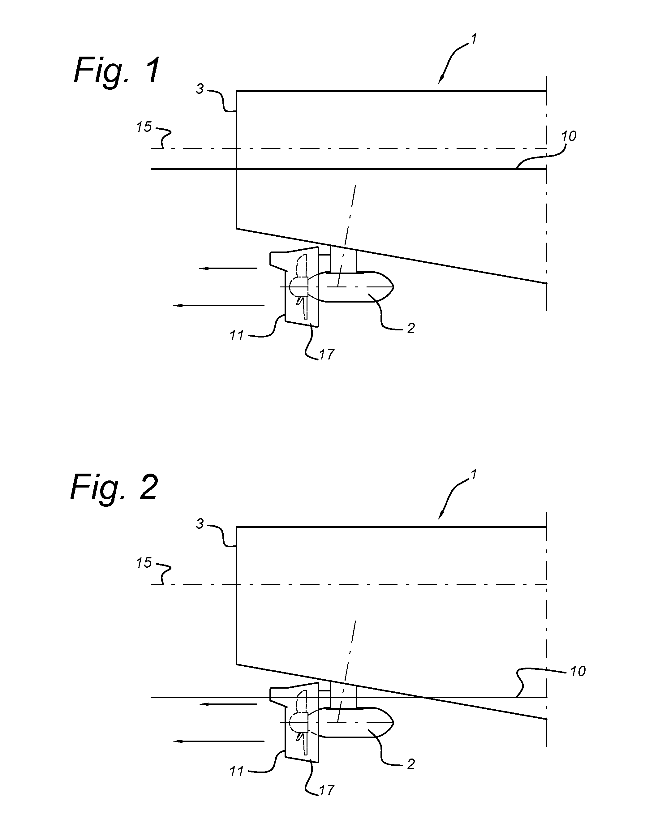
[0042]In FIG. 1, a vessel is designated overall by 1. According to the present invention, this is a relatively large vessel, such as an inland vessel, coaster or larger vessel. The length of the vessel is preferably greater than 20 or 40 metres. The driving power used for such vessels may, for example, be in the range of many kilowatts to several megawatts. The vessel is designated overall by 1 and is provided with a pod 2 at the rear side which is designated by 3. The pod 2 comprises a jet pipe 17 with an inlet delimited by a peripheral edge 11. The waterline in FIG. 1 is indicated by 10 and the longitudinal axis of the hull is indicated by 15. FIG. 1 illustrates the loaded state in which the propeller is entirely under the waterline.

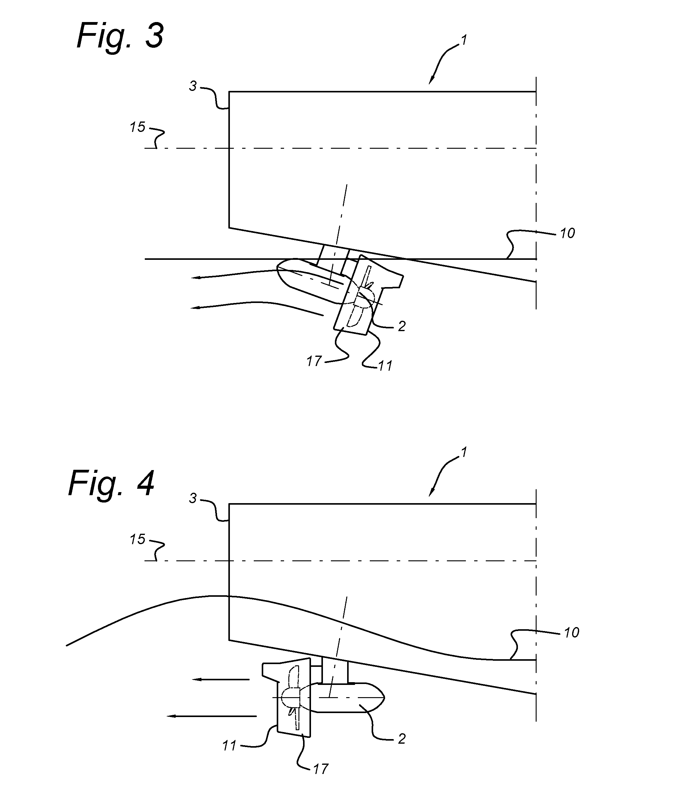
[0043]FIG. 2 illustrates the same vessel 1 in an unladen state, in which the pod is attached in the manner customary in the prior art. It can be seen that the pod, and in particular its propeller, and the inlet of the jet pipe 17 are above the waterlin...


PUM


Abstract

A vessel and a method for driving a vessel. The vessel is provided with a pod arranged at the rear side thereof which is arranged rotatably with respect to the vessel. Rotation is effected about an axis which deviates slightly from the vertical. The axis of the propeller shaft forms an angle which is smaller than 90° with the axis of rotation of the pod. As a result of this combined positioning of the rotation shaft of the pod and the positioning of the propeller shaft, the axis of the propeller shaft with respect to the horizontal will vary when the pod is rotated depending on the rotation position of the pod. This permits optimum adaptation to the various operating conditions of the propeller position.

Description

FIELD OF THE INVENTION[0001]The invention relates to a water-displacement vessel comprising a hull with a longitudinal axis, comprising a bottom and comprising a pod drive arranged close to the bottom, said pod drive being provided with a housing containing a propeller shaft which protrudes through the housing and to which propeller shaft a propeller is attached at a propeller end, and a drive for said propeller shaft, which propeller shaft defines a first axis, which housing is rotatable with respect to the hull between a rearward position and a forward position about a rotation shaft which defines a second axis which is not vertical and forms an angle (α) of 40°-90°, preferably between 60°-80°, with the first axis.[0002]More particularly, the present invention relates to relatively large vessels, i.e. vessels having a length of more than 20 metres and in particular more than 50, or even more than 80, metres and having a water displacement of 500 tons or more. The invention also re...

Claims


Application Information

Patent Timeline
Patent Type & Authority Applications(United States)
IPC IPC(8): B63H5/125B63H5/14B63H5/08B63B1/04
CPCB63H5/125B63H5/08B63H5/14B63B1/04B63H25/42B63H2005/1254
Inventor VAN DER LAAN, MARKUSKOELMAN, HERBERT JANVERHAAR, JANDE BLAEIJ, DIRK JOHANNES
Owner BLUE THRUSTER
Why Eureka
Try Eureka