Engine having composite cylinder block

a composite cylinder block and engine technology, applied in the direction of cylinders, machines/engines, casings, etc., can solve the problems of cast iron cylinder blocks having a low strength-to-weight ratio, affecting the performance of the engine, so as to reduce the size and wear of the combustion chamber, reduce the volume-to-weight ratio, and reduce the friction coefficient

Active Publication Date: 2015-06-11
FORD GLOBAL TECH LLC
View PDF10 Cites 23 Cited by
  • Summary
  • Abstract
  • Description
  • Claims
  • Application Information

AI Technical Summary

Benefits of technology

[0002]Engine cylinders are typically formed by attaching cylinder heads to cylinder blocks. In engine design there are trade-offs between strength, weight, and other material properties of materials used to construct the cylinder head and block. For example, iron has been used to manufacture cylinder blocks. Cast iron may have several benefits over other materials such as a smaller volume to strength ratio and a smaller friction coefficient, decreasing the engine's size and combustion chamber wear. However, cast iron cylinder blocks may have a low strength to weight ratio, is more susceptible to corrosion, and has undesirable heat transfer characteristics. To reduce weight and increase heat transfer to water jackets, cylinder block may be cast out of aluminum. However, aluminum cylinder blocks have several drawbacks, such as high friction coefficients and larger volume to strength ratios.
[0003]U.S. Pat. No. 5,370,087 discloses an engine having a composite cylinder case enclosing metal cylinder banks. The inventors have recognized several disadvantages with the cylinder block disclosed in U.S. Pat. No. 5,370,087. Firstly, the cylinder case enclosing the cylinder banks is spaced away from the cylinder banks to enable coolant to flow around the cylinders. This type of arrangement decreases the structural integrity of the engine when compared to engines cast via a single continuous piece of metal. Therefore, forces transferred to the engine via external components, such as the transmission, may damage the cylinder case. As a result, the longevity of the engine is decreased.
[0005]In this way, a composite material integrally molded with a cylinder liner may be used to form a portion of the engine to increase the engine's strength to weight ratio. Furthermore, the cylinder liner may comprise a metal or other suitable material having more desirable abrasion and heat transfer characteristics around the combustion chambers. In this way, selected portions of the cylinder block may be designed with different materials to increase the engine's strength to weight ratio without compromising desired combustion chamber characteristics. Moreover, integrally molding the cylinder liner with the cylinder block increases the coupling strength of the block assembly.
[0006]The cylinder liner may include various structural features providing greater coupling strength between the cylinder liner and cylinder block. For example, the liner may include a block attachment recess in a top deck of the cylinder liner as well as a block attachment lip extending around a peripheral surface of the liner. The contours of these features provide a greater amount of bonding strength between the thermo-molded composite cylinder block and the cylinder liner during molding. Additionally, the top deck may include openings in fluidic communication with a water jacket cavity. The openings enable a filler material, such as wax, to flow out of the mold during manufacturing. In this way, the water jacket cavity may be formed during manufacturing. Additionally, the openings in the top deck also enable vapor to escape the cylinder block water jacket during engine operation.

Problems solved by technology

However, cast iron cylinder blocks may have a low strength to weight ratio, is more susceptible to corrosion, and has undesirable heat transfer characteristics.
However, aluminum cylinder blocks have several drawbacks, such as high friction coefficients and larger volume to strength ratios.
This type of arrangement decreases the structural integrity of the engine when compared to engines cast via a single continuous piece of metal.
Therefore, forces transferred to the engine via external components, such as the transmission, may damage the cylinder case.
As a result, the longevity of the engine is decreased.

Method used


Image

  • Engine having composite cylinder block
  • Engine having composite cylinder block
  • Engine having composite cylinder block

Examples


Embodiment Construction

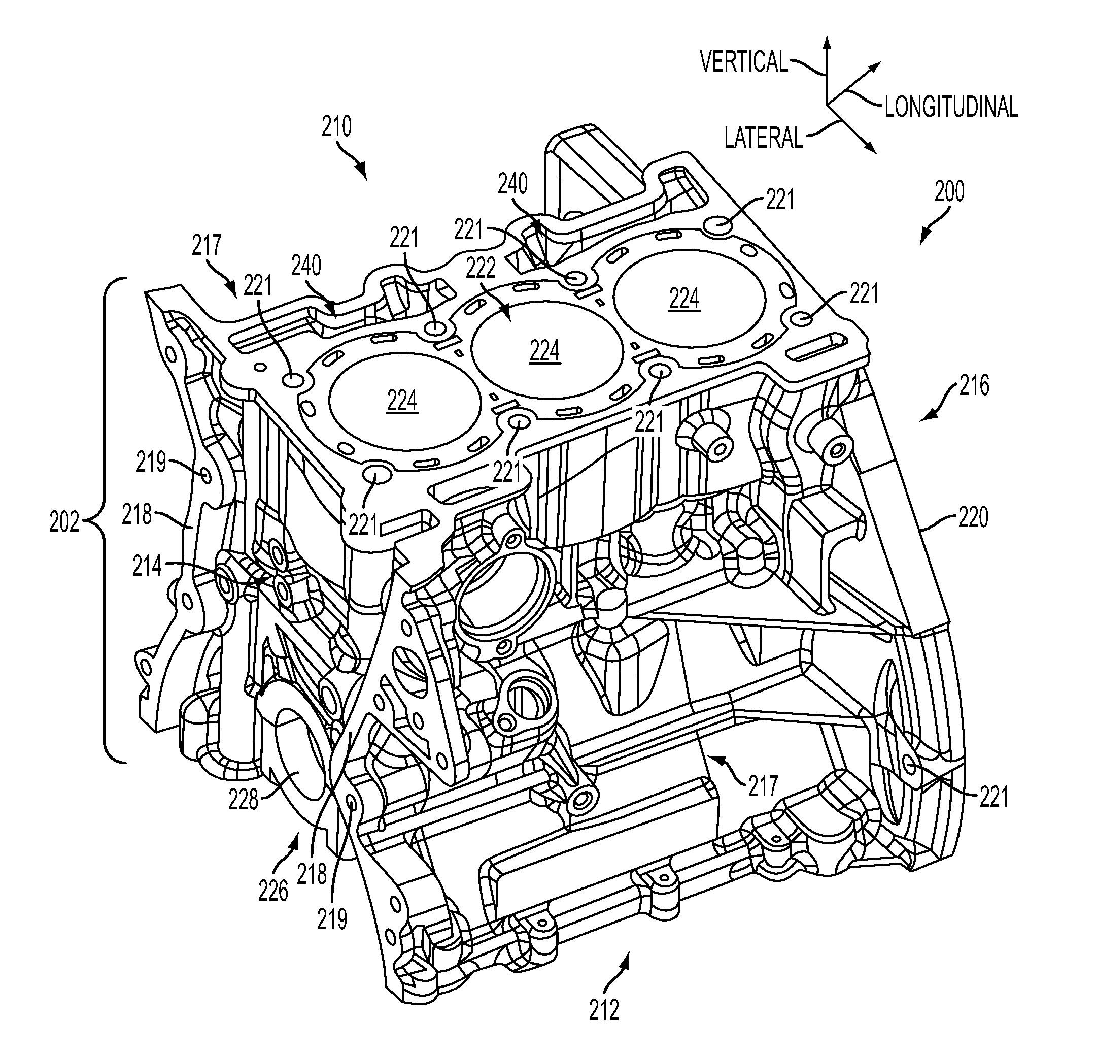
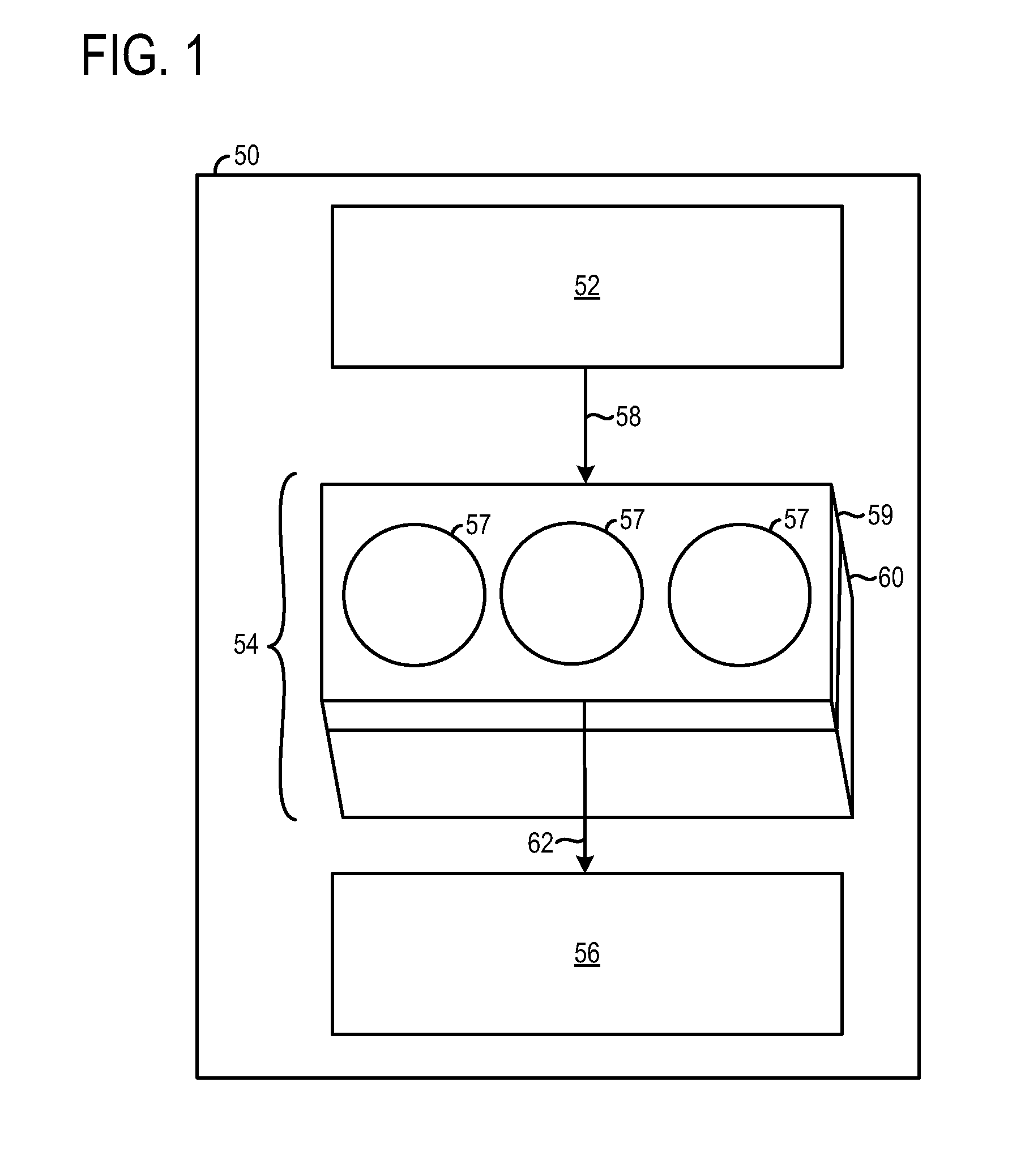
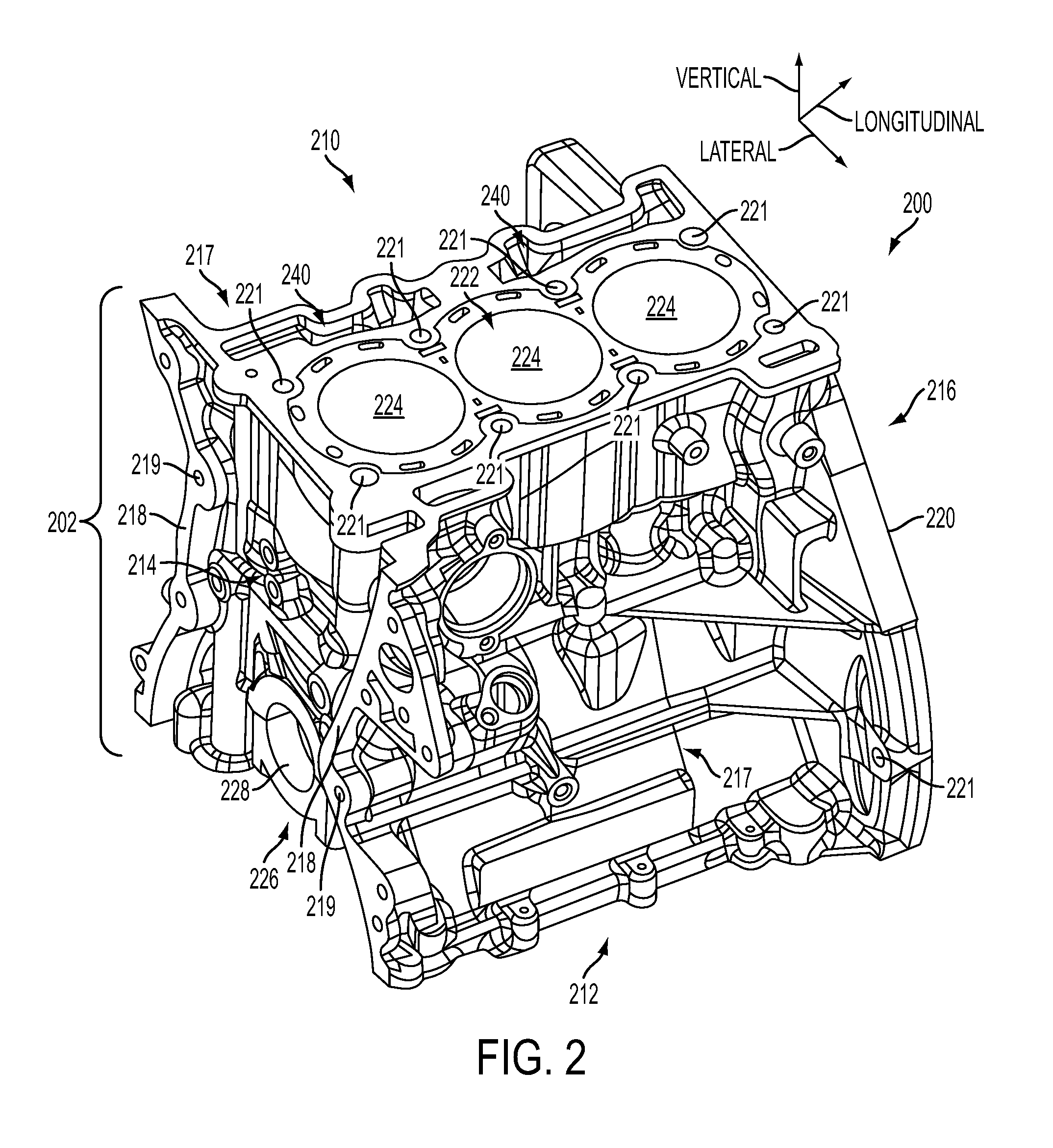
[0017]An engine having a composite cylinder block with an integrally molded cylinder liner defining the boundary of at least one cylinder described herein. The cylinder liner may be constructed out of a metallic material while the cylinder block may be constructed out of a thermal-set or thermo-molded composite material, such as a polymeric material, carbon fiber, etc. In this way, a material having a high strength to weight ratio may be used to construct the block surrounding the cylinder liner. Therefore, a desired structural integrity of the block may be maintained while decreasing the weight of the block or the structural integrity of the block may be increased without increasing the block's weight. Furthermore, providing an integrally molded metallic cylinder liner in the composite cylinder block enables a different material better suited to handle the heat and pressure generated via combustion to be used for the combustion chambers. In this way, the characteristics of various ...


PUM


Abstract

An engine is provided. The engine includes a thermo-molded composite cylinder block including a front engine cover attachment interface and a transmission attachment interface. The engine further includes a cylinder liner comprising a different material than a composite cylinder block and integrally molded with the composite cylinder block, the cylinder liner defining a portion of a boundary of a cylinder and including a top deck at least partially extending across a water jacket cavity surrounding the cylinder.

Description

FIELD[0001]The present disclosure relates to an engine having a thermal-molded composite cylinder block and cylinder liners integrated into the cylinder block.BACKGROUND AND SUMMARY[0002]Engine cylinders are typically formed by attaching cylinder heads to cylinder blocks. In engine design there are trade-offs between strength, weight, and other material properties of materials used to construct the cylinder head and block. For example, iron has been used to manufacture cylinder blocks. Cast iron may have several benefits over other materials such as a smaller volume to strength ratio and a smaller friction coefficient, decreasing the engine's size and combustion chamber wear. However, cast iron cylinder blocks may have a low strength to weight ratio, is more susceptible to corrosion, and has undesirable heat transfer characteristics. To reduce weight and increase heat transfer to water jackets, cylinder block may be cast out of aluminum. However, aluminum cylinder blocks have severa...

Claims


Application Information

Patent Timeline
Patent Type & Authority Applications(United States)
IPC IPC(8): F02F1/18
CPCF02F1/18F02F1/004F02F2200/00F02F1/10F02F1/102F02F1/108F02F7/0007F02F2200/06F05C2253/04
Inventor MAKI, CLIFFORD E.WILLIAMS, RICK L.
Owner FORD GLOBAL TECH LLC
Why Eureka
Try Eureka