
Diffusing member, exhaust gas purification device, and use of diffusing member in exhaust gas purification device

a technology of exhaust gas purification device and diffusing member, which is applied in the direction of machines/engines, separation processes, transportation and packaging, etc., can solve the problems of not being able to sufficiently increase the inner diameter of the exhaust pipe or elongate the length of the exhaust pipe, so as to reduce the temperature of the exhaust gas, easy to dispose, and less susceptible to corrosion

Active Publication Date: 2020-12-29
IBIDEN CO LTD
View PDF15 Cites 0 Cited by
  • Summary
  • Abstract
  • Description
  • Claims
  • Application Information

AI Technical Summary

Benefits of technology

[0007]The urea SCR system injects a urea solution into an exhaust pipe, and the heat of exhaust gas causes hydrolysis, generating ammonia that acts as a reducing agent. At this time, if the temperature inside the exhaust pipe is too low, the hydrolysis and thermal degradation of the urea solution do not proceed properly, and by-products (hereinafter also referred to as by-products of the urea solution) are likely to be generated. The metal static mixer disclosed in Patent Literature 1, when used in the urea SCR system, not only reduces the efficiency of NOx purification reaction in a catalyst carrier due to a decrease in the exhaust gas temperature, but is also more susceptible to corrosion by the by-products of the urea solution since the by-products of the urea solution are more corrosive than ammonia. This has created a demand for a static mixer for use in the urea SCR system, which has measures not only against a decrease in the exhaust gas temperature but also against corrosion by by-products of the urea solution.
[0045]In use of the diffusing member of the present invention, the diffusing member can be easily disposed in the exhaust pipe, for example, by welding the exposed parts of the metal member inside the exhaust pipe.

Problems solved by technology

However, due to restrictions on the structure of vehicles and other factors, it may not be possible to sufficiently increase the inner diameter of the exhaust pipe or to sufficiently elongate the length of the exhaust pipe.

Method used


Image

  • Diffusing member, exhaust gas purification device, and use of diffusing member in exhaust gas purification device
  • Diffusing member, exhaust gas purification device, and use of diffusing member in exhaust gas purification device
  • Diffusing member, exhaust gas purification device, and use of diffusing member in exhaust gas purification device

Examples


Embodiment Construction

[0050]The diffusing member of the present invention is described in detail below.

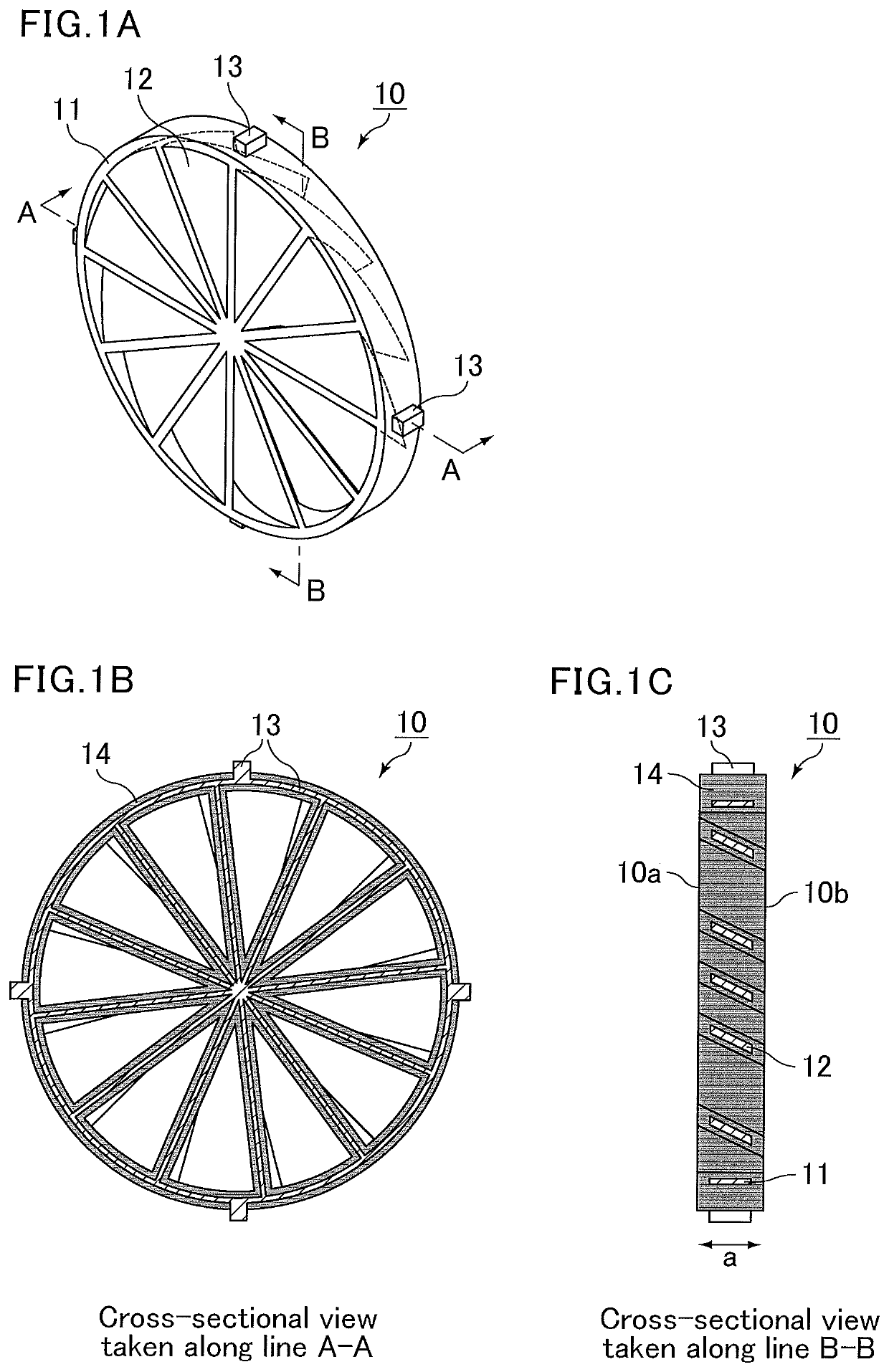
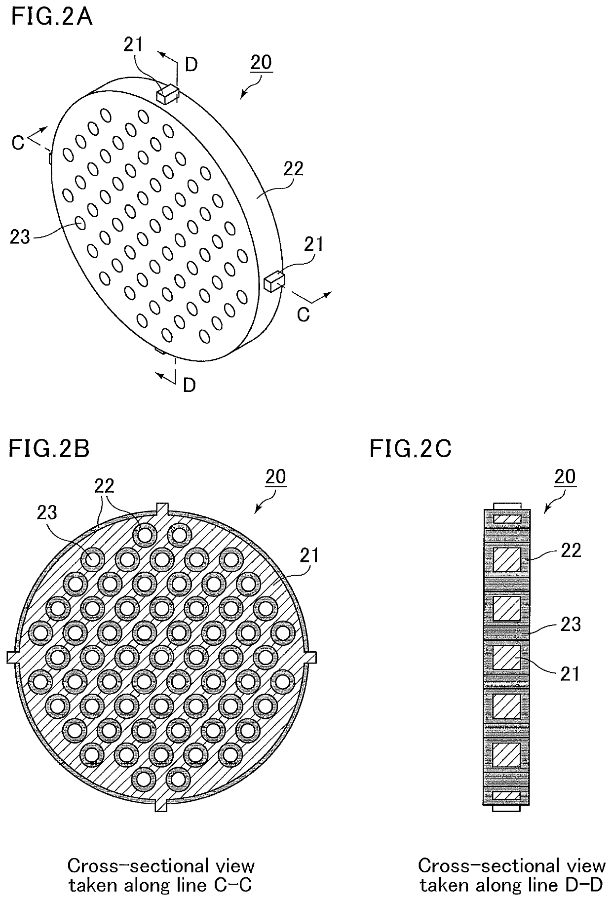
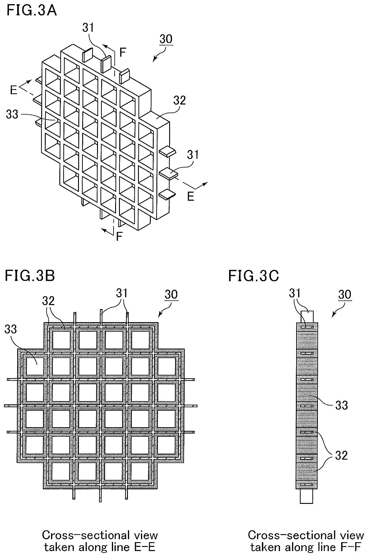
[0051]The diffusing member of the present invention includes a ceramic member and a metal member, wherein the volume of the ceramic member is larger than the volume of the metal member. In other words, the diffusing member is mainly formed of ceramic materials. Thus, the diffusing member can suppress a decrease in the exhaust gas temperature, as compared to diffusing members made of only metal.

[0052]In the diffusing member of the present invention, the ceramic member surrounds the metal member in such a manner that the metal member is partially exposed. That is, the diffusing member of the present invention can be easily disposed in the exhaust pipe, for example, by welding the exposed parts of the metal member inside the exhaust pipe.

[0053]In addition, the diffusing member is less susceptible to corrosion by by-products of the urea solution because the surface of the region where the metal member is no...


PUM

PropertyMeasurementUnit
porosityaaaaaaaaaa
thicknessaaaaaaaaaa
thicknessaaaaaaaaaa

Abstract

The diffusing member of the present invention is disposed in an exhaust pipe to partially block exhaust gas flowing in from upstream of the exhaust pipe, the diffusing member including a ceramic member and a metal member, wherein the ceramic member surrounds the metal member in such a manner that the metal member is partially exposed, and the volume of the ceramic member constituting the diffusing member is larger than the volume of the metal member constituting the diffusing member.

Description

TECHNICAL FIELD[0001]The present invention relates to diffusing members, exhaust gas purification devices, and use of a diffusing member in an exhaust gas purification device.BACKGROUND ART[0002]Diesel engines entail generation of NOx. Thus, methods for removing NOx are required. A selective catalyst reduction system that uses urea as a reducing agent (urea SCR system) has been put into practical use for removal of NOx.[0003]The urea SCR system injects a urea solution into an exhaust pipe. The injected urea solution undergoes hydrolysis and thermal degradation by heat of exhaust gas and is converted into ammonia, acting as a reducing agent that reduces NOx into N2. Thus, sufficient reduction of NOx in exhaust gas requires sufficient mixing of the exhaust gas with ammonia as the reducing agent.[0004]Sufficient mixing of exhaust gas in the exhaust pipe is important not only in the urea SCR system but also in cases where the urea SCR system is used in combination with various sensors.[...

Claims


Application Information

Patent Timeline
Patent Type & Authority Patents(United States)
IPC IPC(8): B01D53/94B01F5/06B01F5/00B01F3/04F01N3/28B01F5/04F01N3/20F01N3/24F01N13/08F01N3/08F01N13/16B01F23/10
CPCF01N13/08B01F5/00F01N3/2892B01F5/0688B01F5/0618F01N3/24B01F5/0473F01N3/08F01N3/208B01F3/0446B01D53/9431B01F5/0057B01F5/0693B01F3/04049B01F2005/0097F01N2450/22B01F2005/0017F01N2240/20F01N2570/14B01F2005/0639F01N2610/1453F01N2510/08Y02T10/12F01N2610/02F01N2260/18F01N2530/02F01N13/16B01F23/2132B01F2025/913B01F2025/9321B01F25/3141B01F25/4316B01F25/431974B01F25/4523B01F25/4521B01F25/00B01F23/232B01F25/10
Inventor KARIYA, SATORUMUTSUDA, FUMIYUKINAKAMURA, TOMOYOSHISUGIURA, YUYAITO, YASUTAKA
Owner IBIDEN CO LTD
Learn More