
Reinforced composite cylinder block

a composite cylinder block and reinforced technology, applied in the direction of machines/engines, other domestic objects, mechanical equipment, etc., can solve the problems of low strength to weight ratio, undesirable heat transfer characteristics, and more susceptible to corrosion of cast iron cylinder blocks, so as to reduce the size of the engine, reduce the friction coefficient, and reduce the volume to strength ratio

Active Publication Date: 2016-08-04
FORD GLOBAL TECH LLC
View PDF6 Cites 0 Cited by
  • Summary
  • Abstract
  • Description
  • Claims
  • Application Information

AI Technical Summary

Benefits of technology

The patent text describes a method of reinforcing engine blocks with metal strips to reduce weight and increase strength. The metal strips are positioned in both a transverse and longitudinal direction to provide additional reinforcement along specific paths that may experience higher loads. This helps improve the engine's performance and structural stability while maintaining a lighter weight. The method also reduces adverse effects of non-uniform fiber fill in the polymer matrix during molding. Overall, the method allows for improved engine block strength while reducing weight.

Problems solved by technology

However, cast iron cylinder blocks may have a low strength to weight ratio, may be more susceptible to corrosion, and may have undesirable heat transfer characteristics.
For example, injection molding of fiber reinforced composite material to form engine blocks may result in non-uniform distribution of the reinforcing fibers.
As an example, the reinforcing fibers may be unevenly distributed along critical load pathways of the engine block.
In another example, the composite material by itself may not possess desired mechanical properties particularly along pathways encountering dynamic loads, structural loads, thermal loads, and loads from attachment to external devices.

Method used


Image

  • Reinforced composite cylinder block
  • Reinforced composite cylinder block
  • Reinforced composite cylinder block

Examples


Embodiment Construction

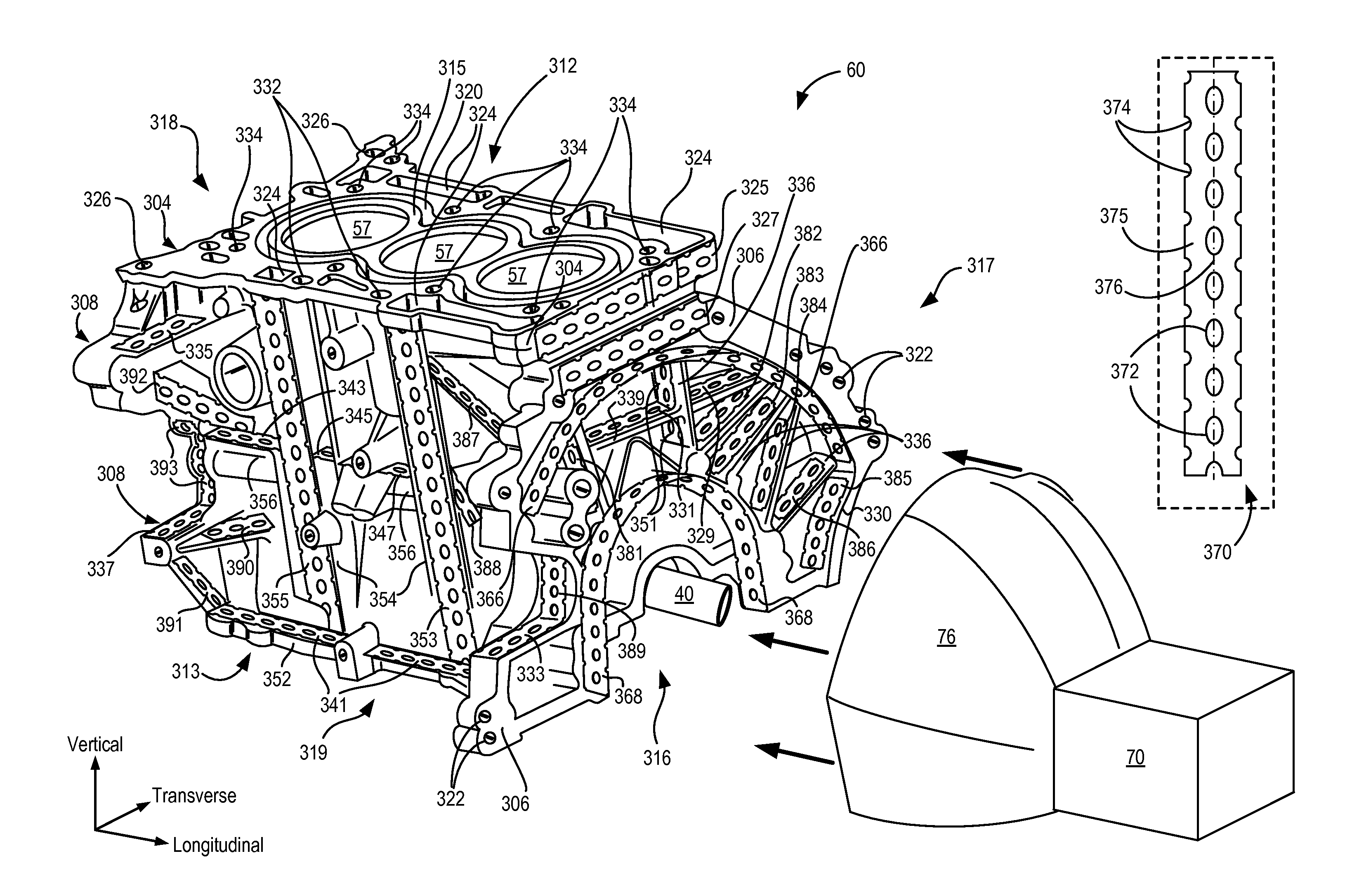
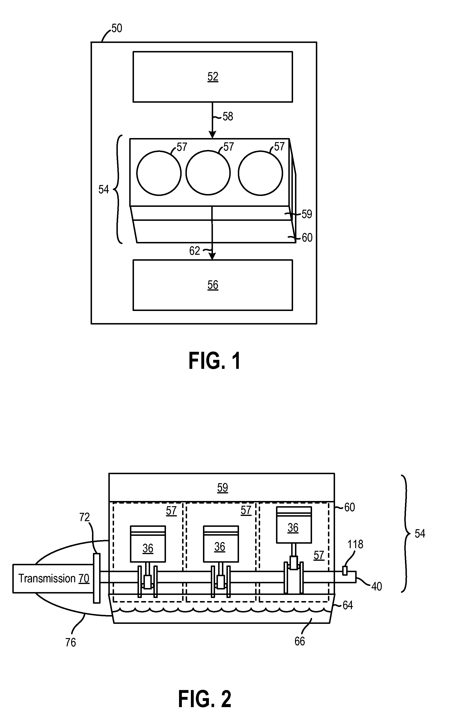
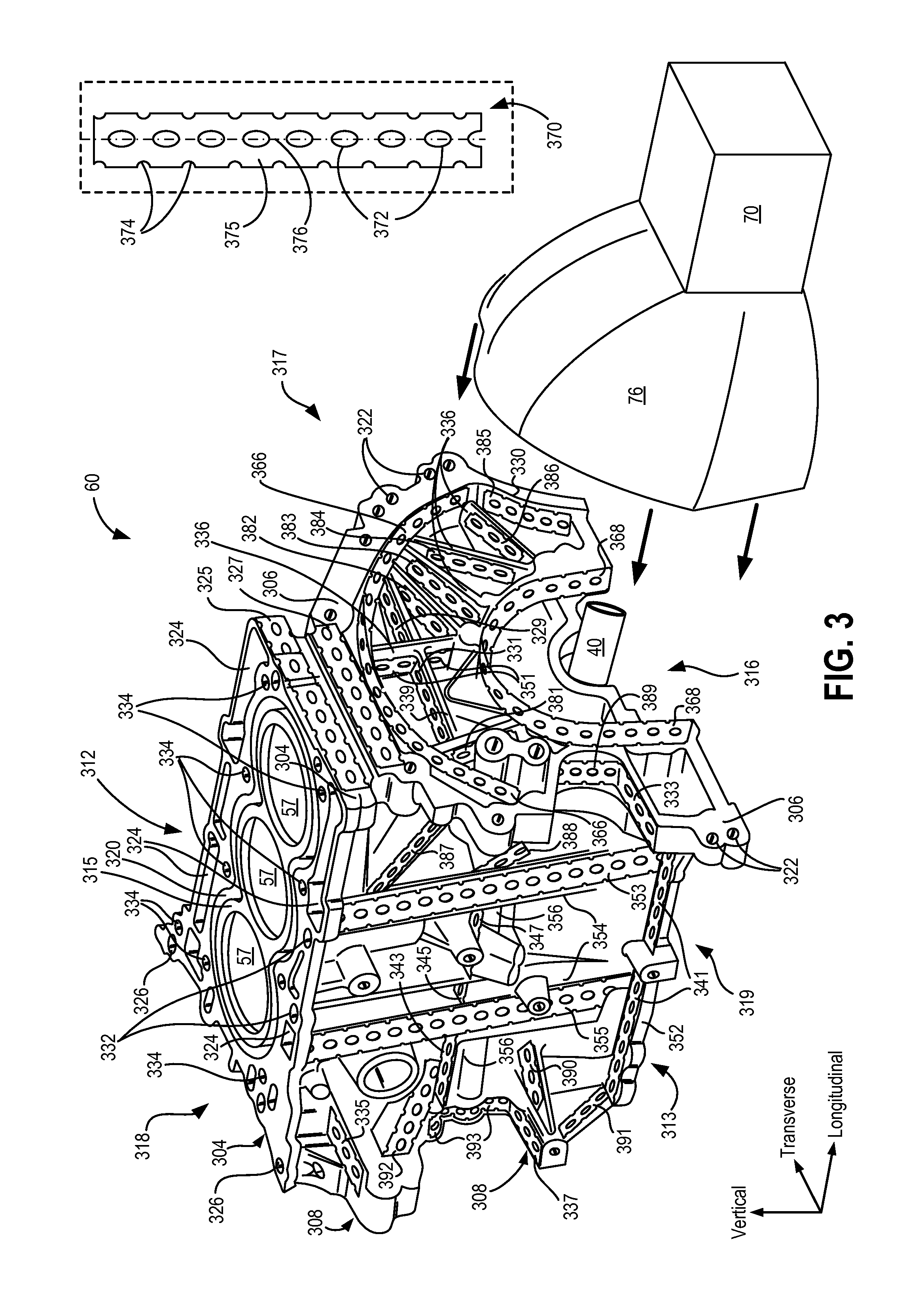
[0014]The following detailed description relates to forming an engine block of an engine in a vehicle, such as the engine depicted in FIG. 2 included in the vehicle of FIG. 1. The engine block may be manufactured from a thermoset composite material with metal reinforcing strips included at specific locations (FIG. 3). The thermoset composite material may include a matrix comprising a thermoset polymer with fibers used for matrix reinforcement. The metal reinforcing strips may be positioned along different directions of the engine block including longitudinal, transverse, vertical directions. As such, the specific locations for positioning the reinforcing strips may include pathways in the engine block that experience higher critical loads. The reinforcing strips may be positioned at desired locations within a mold of the engine block prior to injecting the thermoset composite material. Upon injecting the thermoset composite material, the strips may be encapsulated by the thermoset c...


PUM

PropertyMeasurementUnit
Thicknessaaaaaaaaaa
Lengthaaaaaaaaaa
Widthaaaaaaaaaa

Abstract

Systems and methods are provided for forming an engine comprising a thermoset composite engine block. One example method includes reinforcing the engine block with a plurality of metal strips, wherein a first portion of the plurality of metal strips are positioned in a substantially transverse direction of the engine block and a second portion of the plurality of metal strips are positioned in a substantially longitudinal direction of the engine block. The plurality of metal reinforcing strips may provide additional reinforcement to the engine block.

Description

FIELD[0001]The present disclosure relates to an engine having a thermo-molded composite cylinder block with additional reinforcement strips integrated into the cylinder block.BACKGROUND AND SUMMARY[0002]In engine design there may be trade-offs between strength, weight, and other properties of materials used to construct the cylinder head and block. For example, cast iron has been used to manufacture cylinder blocks. Cast iron may have several benefits over other materials, such as a smaller volume to strength ratio and a smaller friction coefficient, decreasing the engine's size and increasing combustion chamber longevity. However, cast iron cylinder blocks may have a low strength to weight ratio, may be more susceptible to corrosion, and may have undesirable heat transfer characteristics. In order to reduce block weight and increase the amount of heat transferred to water jackets, cylinder blocks may be cast out of aluminum.[0003]A reduction in block weight may also be obtained by ...

Claims


Application Information

Patent Timeline
IPC IPC(8): F02F7/00B29C70/02B29C70/26
CPCF02F7/0095F02F7/0021F02F7/0085B29C70/26B29K2105/12B29K2705/08B29L2031/749B29K2105/20B29C70/023B29C45/14065F02F1/18F05C2201/0412F05C2225/00
Inventor MAKI, CLIFFORD E.ELIE, LARRY DEANBYRD, KEVIN DURANDWILLIAMS, RICK L.BUSCHHAUS, WOLFRAMZALUZEC, MATTHEW JOHN
Owner FORD GLOBAL TECH LLC
Learn More