
Image processing device, tactile sense control method, and recording medium

Active Publication Date: 2015-06-11
CANON KK
View PDF23 Cites 121 Cited by
  • Summary
  • Abstract
  • Description
  • Claims
  • Application Information

AI Technical Summary

Benefits of technology

The invention aims to solve one or more problems, such as overheating, excessive noise, excessive vibration, excessive wear and tear, and inefficient operation. The technical effects of the invention include reducing these problems and improving the overall performance of the system or device that the invention is used in.

Problems solved by technology

However, if an edit process (erasure, line drawing, color painting, or the like of a drawing object) by a touch input onto an input screen provided on a display screen is executed to the drawing object drawn on the display screen by the painting function or the like, there is such a problem that it is difficult to confirm whether or not the edit process of editing the portion touched by the touch operation using a finger, a stylus pen, or the like has actually been executed.
In the case of erasing the drawing object on the display screen as an edit process, the touched portion is hidden by the finger and there is such a problem that it is difficult for the user to confirm whether or not the drawing object which the user wants to erase has been erased.

Method used


Image

  • Image processing device, tactile sense control method, and recording medium
  • Image processing device, tactile sense control method, and recording medium
  • Image processing device, tactile sense control method, and recording medium

Examples


first embodiment

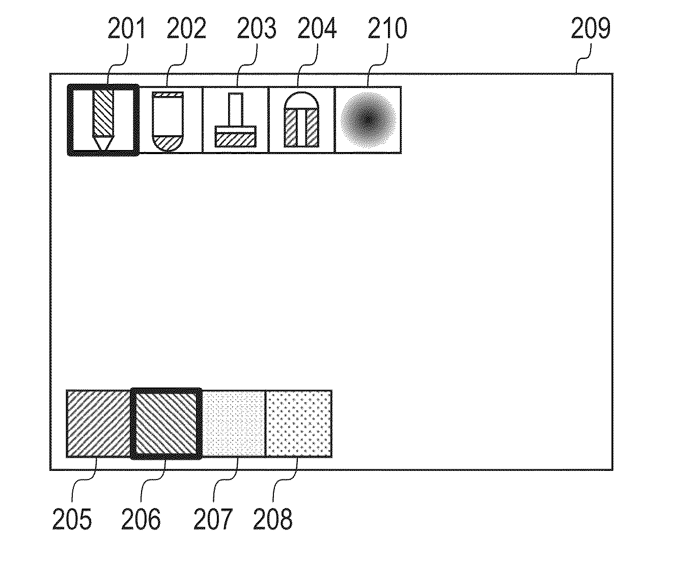
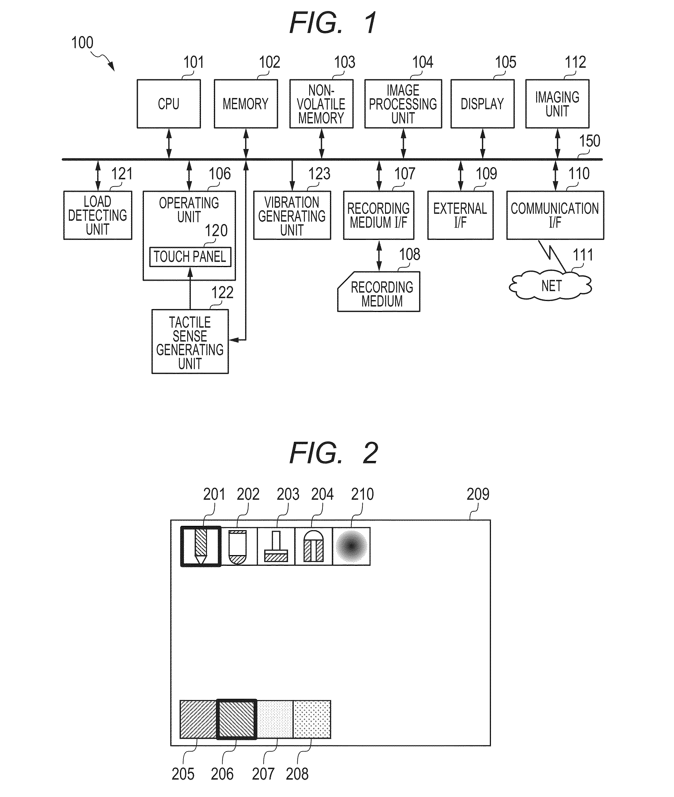
[0021]FIG. 1 is a diagram illustrating an electronic device 100 serving as an image processing device according to the first embodiment. The electronic device 100 can be constructed by a cellular phone, a smartphone, a tablet terminal, or the like. As illustrated in FIG. 1, a CPU 101, a memory 102, a non-volatile memory 103, an image processing unit 104, a display 105, an operating unit 106, a recording medium I / F (interface) 107, an external I / F 109, and a communication I / F 110 are connected to an internal bus 150. An imaging unit 112, a tactile sense generating unit 122, and a vibration generating unit 123 are also connected to the internal bus 150. Each unit connected to the internal bus 150 can mutually transmit and receive data through the internal bus 150.

[0022]The memory 102 has, for example, a RAM (volatile memory or the like using a semiconductor device). The CPU 101 controls each unit of the electronic device 100 by using the memory 102 as a work memory in accordance with ...

second embodiment

[0072]Subsequently, the electronic device 100 according to the second embodiment will be described. In the case of erasing the drawing object drawn by the painting function, on the basis of the pen type of the drawing object as an erasure target, the electronic device 100 according to the second embodiment controls the type of tactile sense which is generated. The electronic device 100 according to the second embodiment will be described hereinbelow with respect to portions different from the electronic device according to the first embodiment.

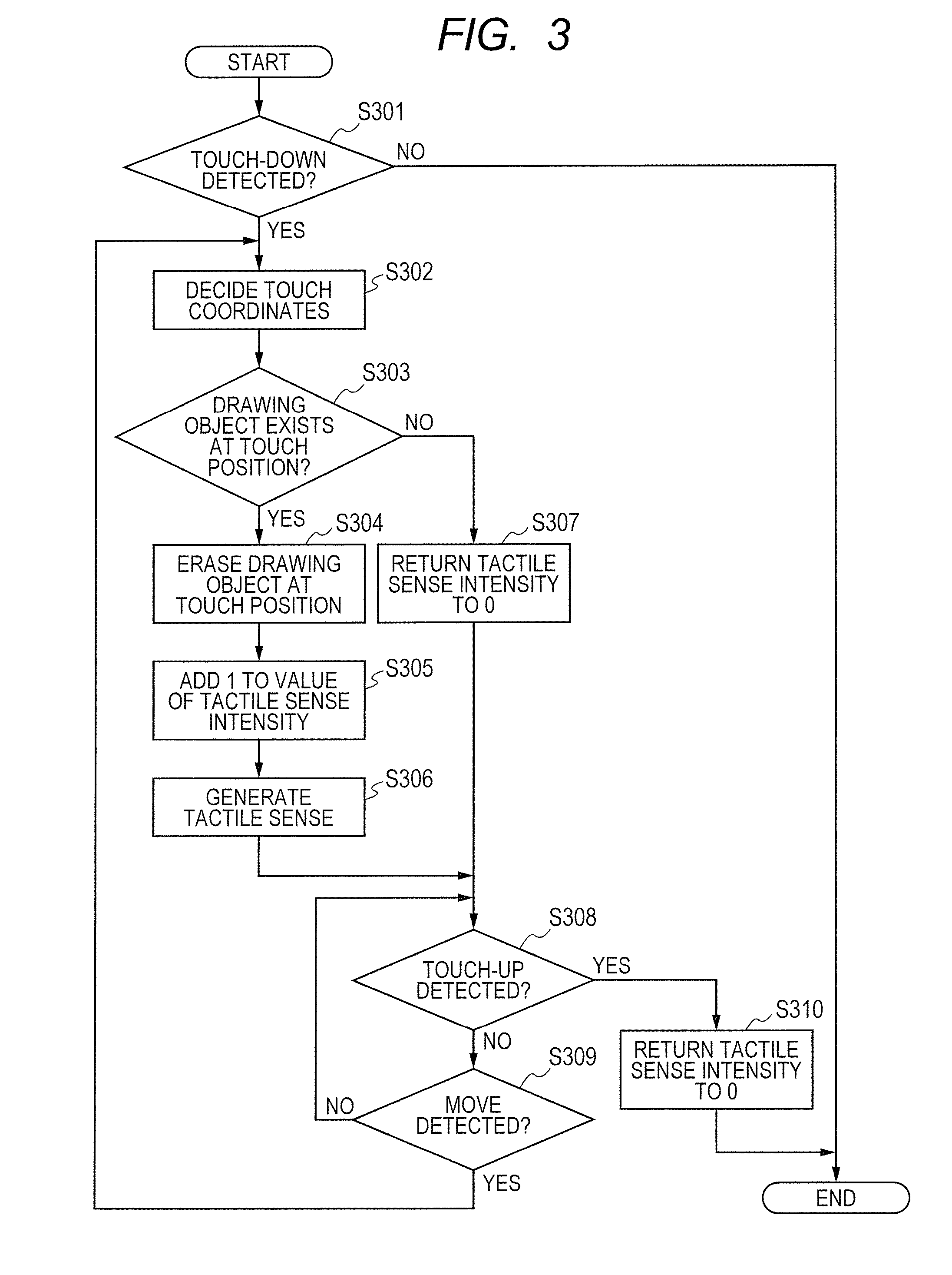
[0073]FIG. 4 is a flowchart illustrating a tactile sense control process by the electronic device 100 according to the second embodiment. Among the processes in the tactile sense control process illustrated in FIG. 4, substantially the same processes as those in the tactile sense control process according to the first embodiment are designated by the same reference numerals.

[0074]In S303, the CPU 101 discriminates whether or not a drawing obje...

third embodiment

[0083]Subsequently, the electronic device 100 according to the third embodiment will be described. In the case of applying a blurring filter to the drawing object, the electronic device 100 according to the third embodiment controls the tactile sense intensity on the basis of a degree of blurring. The electronic device 100 according to the third embodiment will be described hereinbelow with respect to portions different from the electronic devices according to the other embodiments.

[0084]FIG. 7 is a flowchart illustrating a tactile sense control process by the electronic device 100 according to the third embodiment. Among the processes in the tactile sense control process illustrated in FIG. 7, substantially the same processes as those in the tactile sense control process according to the first embodiment are designated by the same reference numerals.

[0085]In S303, the CPU 101 discriminates whether or not a drawing object exists at the touch position. If a drawing object exists, the...


PUM


Abstract

An image processing device according to an embodiment of the invention has: a tactile sense generating unit for generating a stimulus which can be perceived by the user who is touching through a portion touched with an input unit, the input unit being provided in correspondence to a display unit for displaying a drawing object; and a control unit for controlling the tactile sense generating unit so as to generate the stimulus when a touch input is performed to a position corresponding to the drawing object of the input unit and an edit process is executed to the drawing object.

Description

BACKGROUND OF THE INVENTION[0001]1. Field of the Invention[0002]The present invention relates to an image processing device, a tactile sense control method, and a recording medium.[0003]2. Description of the Related Art[0004]In recent years, the number of devices having a touch panel is increasing. Owing to such a feature that the user can freely designate a location on a display screen, many of these devices have an editing function for editing existing images and a painting function. As disclosed in the Official Gazette of Japanese Patent Application Laid-Open No. 2012-124612, the painting function is a function for painting and generating an image itself. In the painting function, the user can select a type and a color of a line and freely draw a line or can erase the drawn line by selecting an icon of an eraser or the like.[0005]However, if an edit process (erasure, line drawing, color painting, or the like of a drawing object) by a touch input onto an input screen provided on a...

Claims


Application Information

Patent Timeline
IPC IPC(8): G06F3/01G06F3/041
CPCG06F3/016G06F3/0416G06F3/0412G06F3/04845G06F3/0488G06T11/60G06F3/04883
Inventor NAKAGAWA, KOICHI
Owner CANON KK
Learn More