
Driving circuit and driving method of display

a driving circuit and display technology, applied in the field of image display, can solve the problem of difficult to precisely control the gray level of the frame, and achieve the effect of consistent oled illumination and precise control of frame brightness

Inactive Publication Date: 2015-06-11
SHENZHEN CHINA STAR OPTOELECTRONICS TECH CO LTD
View PDF8 Cites 12 Cited by
  • Summary
  • Abstract
  • Description
  • Claims
  • Application Information

AI Technical Summary

Benefits of technology

The present invention aims to solve the technical problem of achieving precise control of OLED illuminance and consistent frame brightness. The invention achieves this by equally dividing a frame time and using a digital signal (0 / 1 to turn on or turn off the OLED based on time division. This results in consistent and high-quality OLED illuminance.

Problems solved by technology

However, due to possible manufacturing variations and unreliable control of voltage amplitudes in this method, there likely exists a defect of inconsistent brightness in a frame, and it is hard to control the gray levels of the frame precisely.

Method used


Image

  • Driving circuit and driving method of display
  • Driving circuit and driving method of display
  • Driving circuit and driving method of display

Examples


Embodiment Construction

[0029]Hereinafter, detailed descriptions of the invention are given with combined drawings and preferred embodiments.

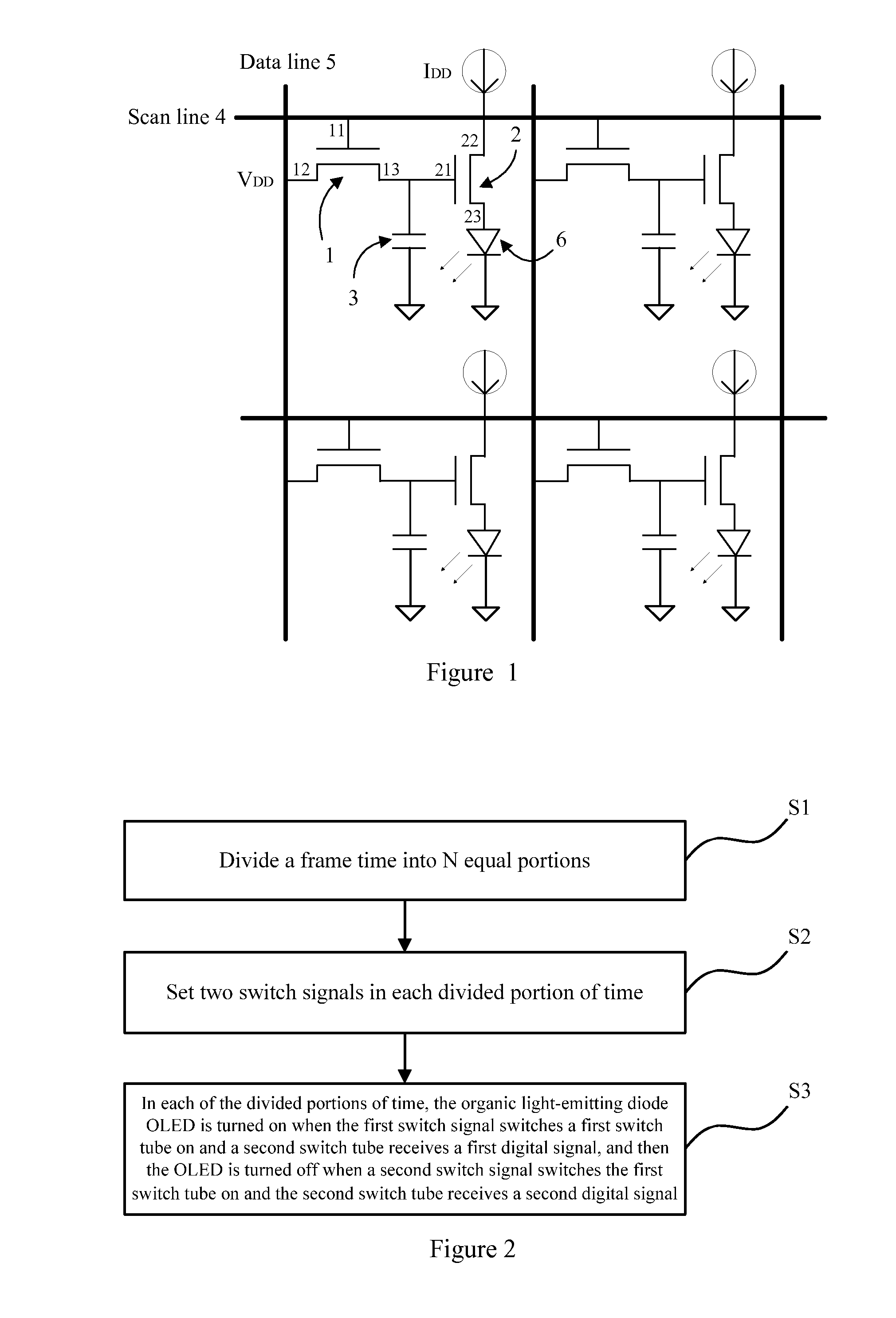
[0030]With reference to FIG. 2, a driving method of a driving circuit of a display according to a first embodiment of the present invention is provided. The driving method includes:

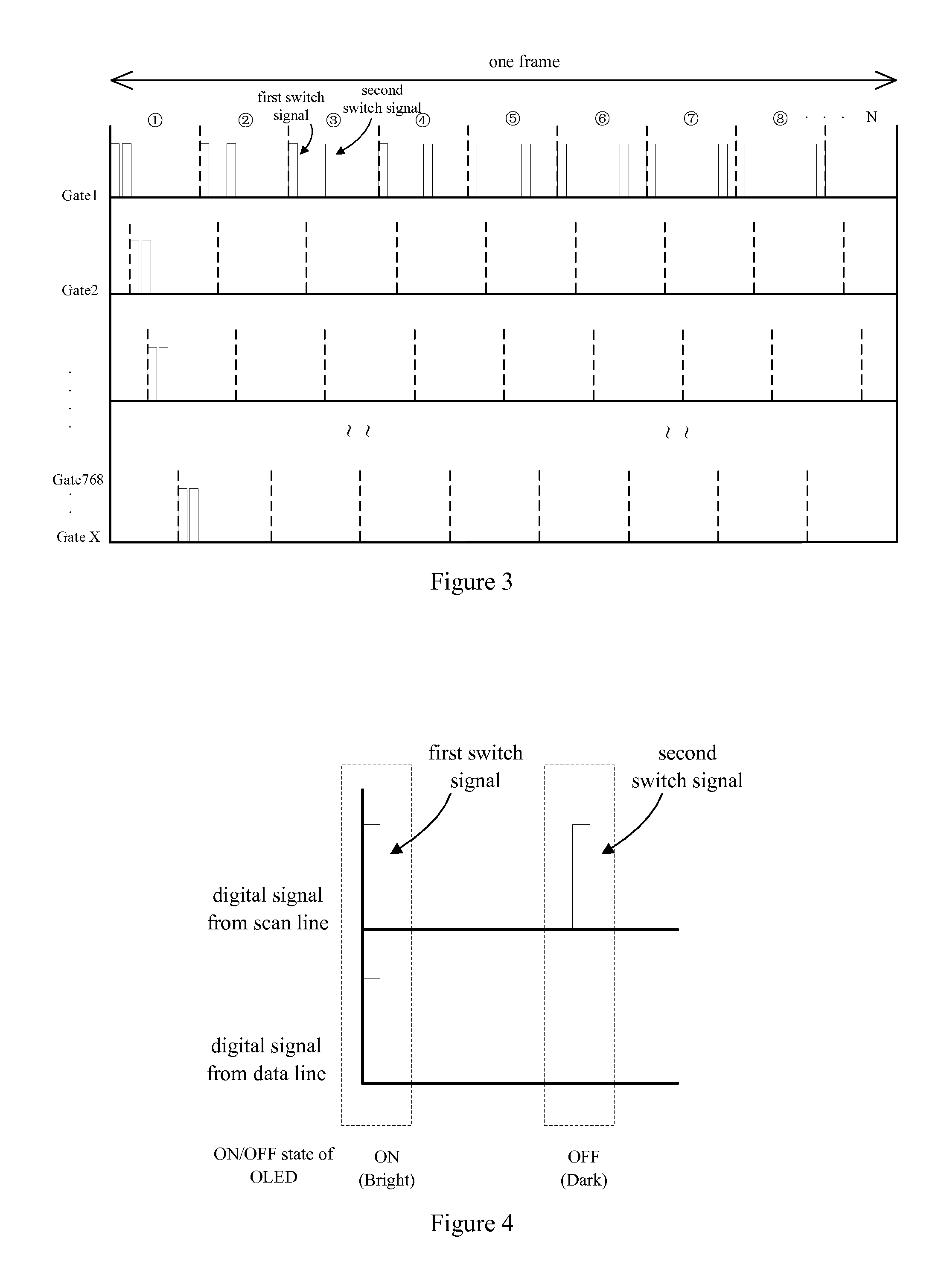
[0031]Step S1: equally dividing a frame time into N divided portions, where N≧1 and N is an integer;

[0032]wherein a frame frequency is 60 / 120 Hz (or a multiple of 60) or 50 / 100 Hz (or a multiple of 50);

[0033]Step S2: setting two switch signals in each of the divided portions of time; and

[0034]Step S3: in each of the divided portions of time, the organic light-emitting diode OLED is turned on when a first one of the switch signals switches a first switch tube on and a second switch tube receives a first digital signal, and then the OLED is turned off when a second one of the switch signals switches the first switch tube on and the second switch tube receives a second digital signal.

[0035]Pra...


PUM


Abstract

Inventive driving circuit and driving method of a display are provided. The driving method includes equally dividing a frame time into N divided portions, where N≧1 and N is an integer; setting two switch signals in each of the divided portions of time; and turning the OLED (6) on when a first switch signal switches the first switch tube (1) on and the second switch tube (2) receives the first digital signal, in each of the divided portions of time, and turning the OLED (6) off when the second switch signal switches the first switch tube (1) on and the second switch tube (2) receives the second digital signal. By equally dividing a frame time, a digital signal (0 / 1) may replace for the conventional analog signal to turn on / off an OLED based on time division. Precise control of frame brightness can be achieved for consistent OLED illuminance.

Description

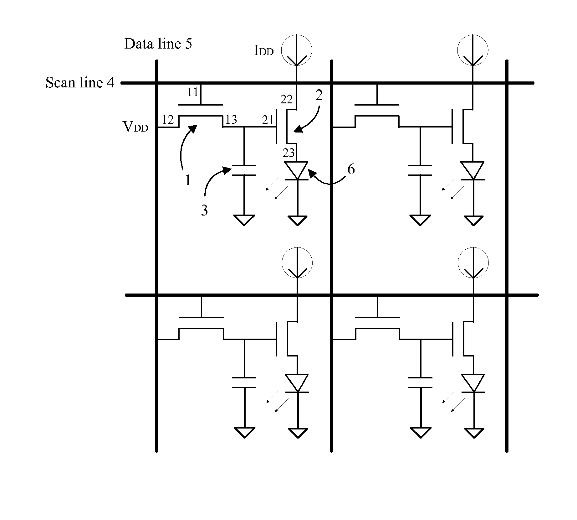
CROSS REFERENCE TO RELATED APPLICATIONS[0001]The present application claims priority to Chinese Patent Application No. 201310650341.9, filed Dec. 6, 2013, and entitled “driving circuit and driving method of display”. The entire contents of the above-mentioned patent application are cited and incorporated herein for reference.FIELD OF THE INVENTION[0002]The present invention relates to a field of image display, and more particularly to driving circuit and driving method of a display.BACKGROUND OF THE INVENTION[0003]A driving circuit of an OLED (organic light-emitting diode) is illustrated in FIG. 1, which includes a first switch tube 1, a second switch tube 2 and a capacitor 3. The first field effect transistor 1 has a gate 11 connected to a scan line 4, a drain 12 connected to a data line 5, and a source 13 connected to a first end of the capacitor 3 and a gate 21 of the second field effect transistor 2. A drain 22 of the second field effect transistor 2 is coupled to a positive vol...

Claims


Application Information

Patent Timeline
Patent Type & Authority Applications(United States)
IPC IPC(8): G09G3/20G09G3/32
CPCG09G3/2025G09G3/325G09G3/3266G09G3/3291G09G2310/0278G09G2320/064G09G2300/0819G09G2310/027G09G2320/0233G09G3/3233G09G2300/0842
Inventor CHEN, YU-YEHCHANG, YUHUAHE, JHEN-WEICHEN, MING-WEI
Owner SHENZHEN CHINA STAR OPTOELECTRONICS TECH CO LTD
Learn More