Electronic radiography system and signal relay device

a technology of electronic radiography and signal relay, which is applied in the field of electronic radiography system, can solve the problems of high introduction cos

Active Publication Date: 2015-06-18
FUJIFILM CORP
View PDF5 Cites 21 Cited by
  • Summary
  • Abstract
  • Description
  • Claims
  • Application Information

AI Technical Summary

Benefits of technology

[0031]According to the present invention, the signal relay device transmits the emission command signal from the emission switch to the electronic radiographic image detection device, and synchronizes the radiation generating apparatus with the electronic radiographic image detection device, and receives the emission enable signal, which represents a time period from the time when the emission is enabled in response to the emission command signal until the time for stopping the emission determined by the AEC function, from the electronic radiographic image detection device, and generates the emission execution signal based on the emission enable signal and the emission command signal. The source control device allows the radiation source to emit the radiation while the emission execution signal is inputted to the source control device. The emission execution signal generated by the signal relay device is inputted to the source control device in place of the conventional emission command signal. Thus, according to the present invention, the AEC function of the electronic radiographic image detection device is utilized without modifying the source control device.

Problems solved by technology

In this modification, the electronic X-ray detection device and the console are replaced while the existing X-ray generating apparatus is used without replacement because the modifications to the entire system results in high introduction cost.

Method used


Image

  • Electronic radiography system and signal relay device
  • Electronic radiography system and signal relay device
  • Electronic radiography system and signal relay device

Examples


Embodiment Construction

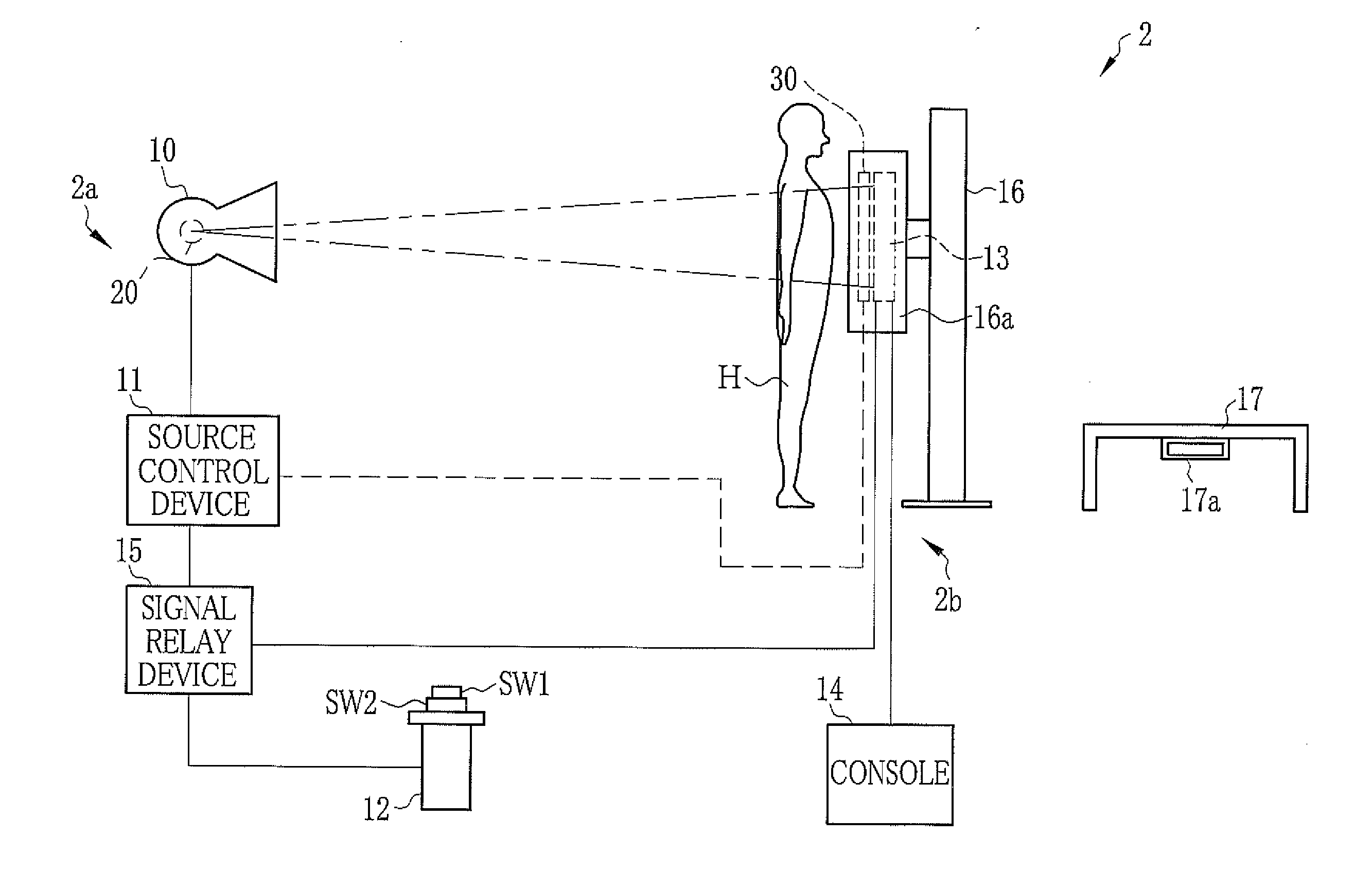
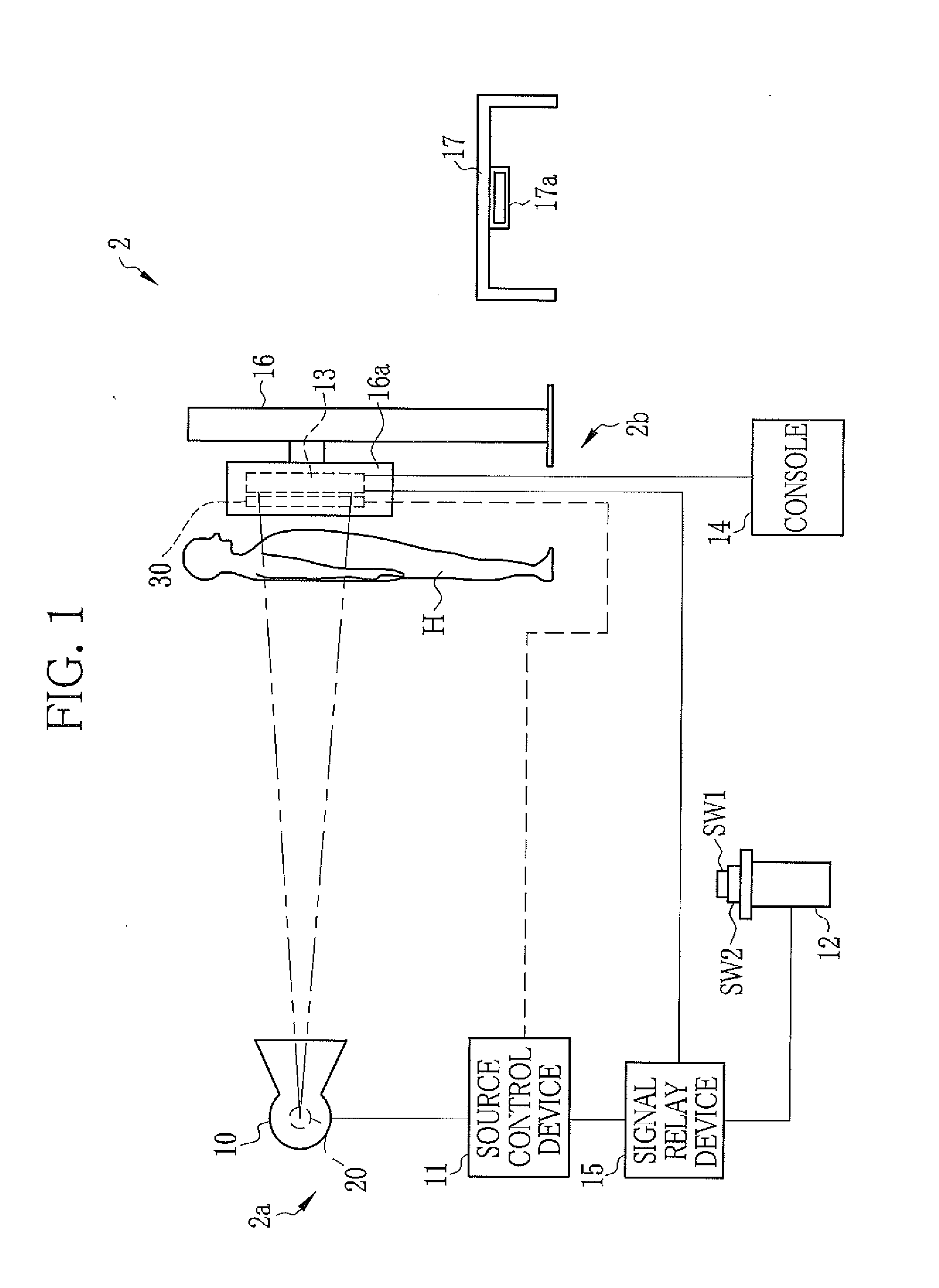
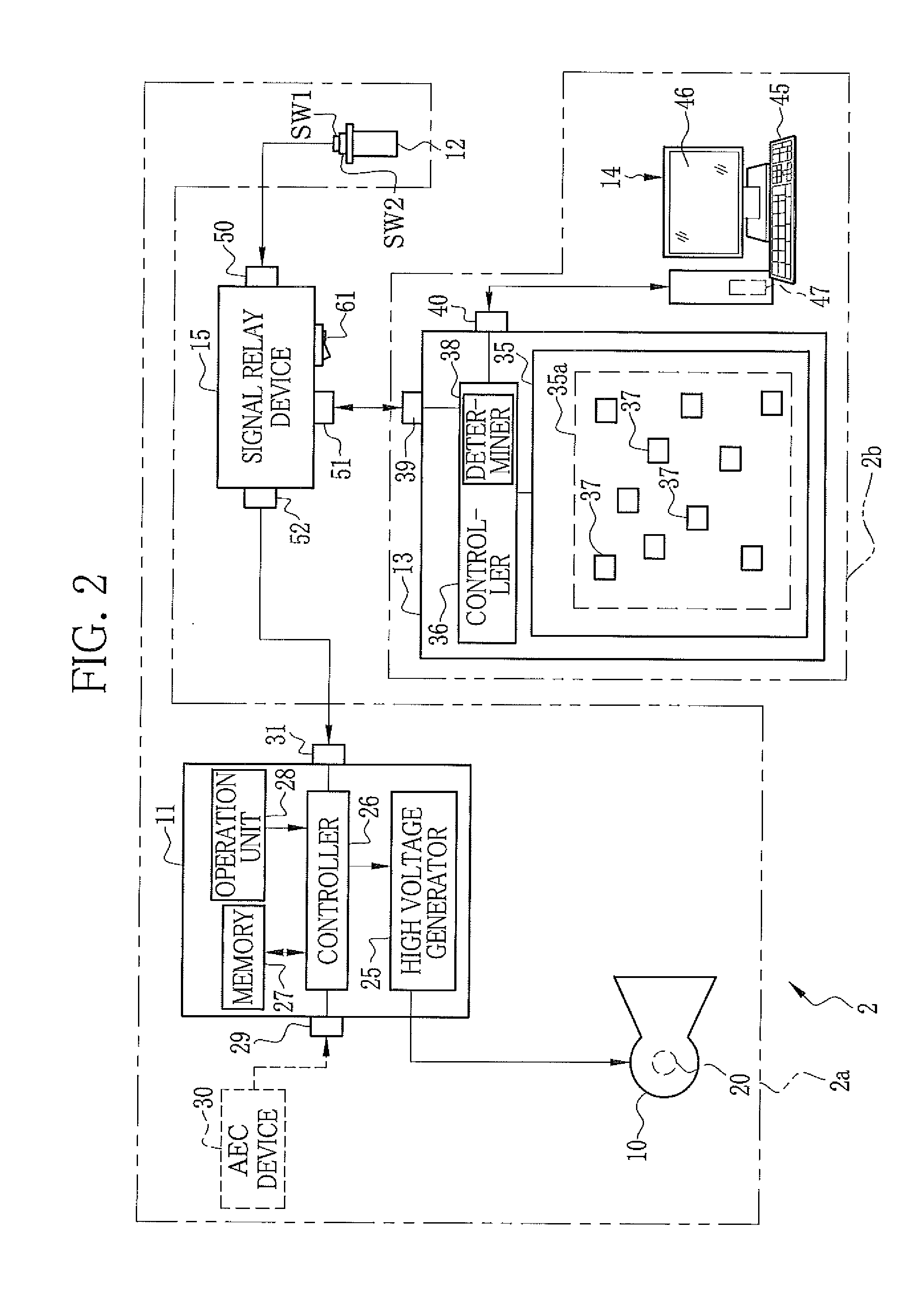
[0042]In FIGS. 1 and 2, an electronic X-ray imaging system 2 is produced by retrofitting or making modifications to an existing or conventional X-ray imaging system. The existing X-ray imaging system comprises an X-ray generating apparatus 2a, an imaging stand 16 that allows imaging of a patient H in a standing position, and an imaging table 17 that allows imaging of a patient H in a lying position. The X-ray generating apparatus 2a comprises an X-ray source 10 that generates X-rays, a source control device 11 that controls operation of the X-ray source 10, and an emission switch 12 that commands the X-ray source 10 to start warm-up and to start emission of the X-rays. The X-ray source 10 is moved along a ceiling or the like by a source moving device (not shown), to be compatible for use by the imaging stand 16 and the imaging table 17. In the existing X-ray imaging system, a film cassette using an X-ray film or an IP cassette 80 (see FIG. 3) using an IP plate is inserted into a hol...


PUM


Abstract

A signal relay device comprises a first connection I / F, to which an emission switch is connected, a second connection I / F, to which an emission signal I / F of an electronic cassette is connected, and a third connection I / F, to which a switch I / F of a source control device is connected, and a signal processing unit. The signal processing unit generates an emission execution signal during a time period in which an emission command signal from the emission switch and an emission enable signal from the electronic cassette are inputted. The source control device drives an X-ray tube to allow X-ray emission while the emission execution signal is inputted.

Description

CROSS-REFERENCE TO RELATED APPLICATIONS[0001]This application is a Continuation of PCT International Application No. PCT / JP2013 / 069476 filed on Jul. 18, 2013, which claims priority under 35 U.S.C. §119(a) to Japanese Patent Application No. 2012-183094, filed Aug. 22, 2012 and Japanese Patent Application No. 2013-109302, filed May 23, 2013. Each of the above applications is hereby expressly incorporated by reference, in its entirety, into the present application.BACKGROUND OF THE INVENTION[0002]1. Field of the invention The present invention relates to an electronic radiography system for imaging radiographic images and a signal relay device.[0003]2. Description Related to the Prior Art[0004]In medical fields, radiography systems, for example, X-ray imaging systems using X-rays are widely used to examine inside human bodies. The X-ray imaging system comprises an X-ray generating apparatus that generates X-rays and an X-ray imaging apparatus for imaging X-ray images generated by the X...

Claims


Application Information

Patent Timeline
Patent Type & Authority Applications(United States)
IPC IPC(8): A61B6/00
CPCA61B6/548A61B6/545A61B6/405A61B6/542A61B6/4233A61B6/4283A61B6/54A61B6/566H04N5/32G01T1/026G01T1/1603G05B1/03G05B11/06G05B13/041G05B19/0423G05B19/0425G05B19/106G05B19/414G05B23/0286H05G1/38H05G1/40H05G1/42H05G1/44H05G1/56
Inventor IMAMURA, RYOU
Owner FUJIFILM CORP
Why Eureka
Try Eureka