Laser orthodontic devices

a laser and orthodontic technology, applied in the field of laser devices, can solve the problems of unattainable other technologies, unsatisfactory success rate of widely accepted approaches, and high degree of spatial and temporal coherence of laser light, so as to reduce the profile, prevent drooling, and maximize patient compliance

Active Publication Date: 2015-06-18
ADVANCED ORTHODONTICS & EDUCATION ASSOC LLC
View PDF6 Cites 64 Cited by
  • Summary
  • Abstract
  • Description
  • Claims
  • Application Information

AI Technical Summary

Benefits of technology

[0057]Any off the shelf on / off switch can be used. Particularly preferred for the intraoral device is an on / off switch with depressible activator (push button switch, rocker switch, or membrane button switch). Membrane button switches are particularly preferred as water proof, having low profile, and being reliable.
[0058]Generally speaking, the laser(s) or LED(s), and battery or other power source, optional on / off switch and circuitry, etc. are placed directly on the bite plate and hermetically sealed with no extraoral protrusions, thus allowing the most compact bite plate, preventing drooling and maximizing patient compliance. In preferred embodiments, the core may contain depressions therein for fitting various components thereinto, thus maintaining the generally planar surface of the bite plate and maintaining a thin cross section.

Problems solved by technology

Although effective, this widely accepted approach takes about twenty-four months on average to achieve success.
Infrared light is used in industrial, scientific, and medical applications, and its power in medical applications has yet to be fully realized.
The emitted laser light is notable for its high degree of spatial and temporal coherence, unattainable using other technologies.
However, carious or decayed tooth structure will emit fluorescence light, resulting in elevated number readings on the display.
Further, no details about the light source are provided and its connection to the tray, so it is unclear how or if the device works.
However, neither device is suitable for orthodontic uses.
However, there is noting to guide the light and much of it will be dissipated without effect, reducing the overall efficacy of the device per unit of power consumed.
Doses lower than the optimum value have less effect, and doses higher than the optimum can even be harmful.
Interestingly, Fugita's results suggests that non-coherent light was ineffective to induce remodeling or induce RANK, and that coherent light was needed.
The authors concluded that because low-intensity laser therapy stimulates tooth movement by altering the biologic responses, and because it does not work by increasing forces or changing mechanics, it does not tax the anchorage.
However, no such device exists and none was described in the human studies, which used a large external laser, designed for other uses.
Further, it may be equally or nearly equally efficacious to use LEDs instead of laser diodes, and any loss in efficacy may be offset by cost, reliability and / or power consumption characteristics.

Method used


Image

  • Laser orthodontic devices
  • Laser orthodontic devices
  • Laser orthodontic devices

Examples


Embodiment Construction

[0082]The following examples are illustrative only and not intended to limit the invention.

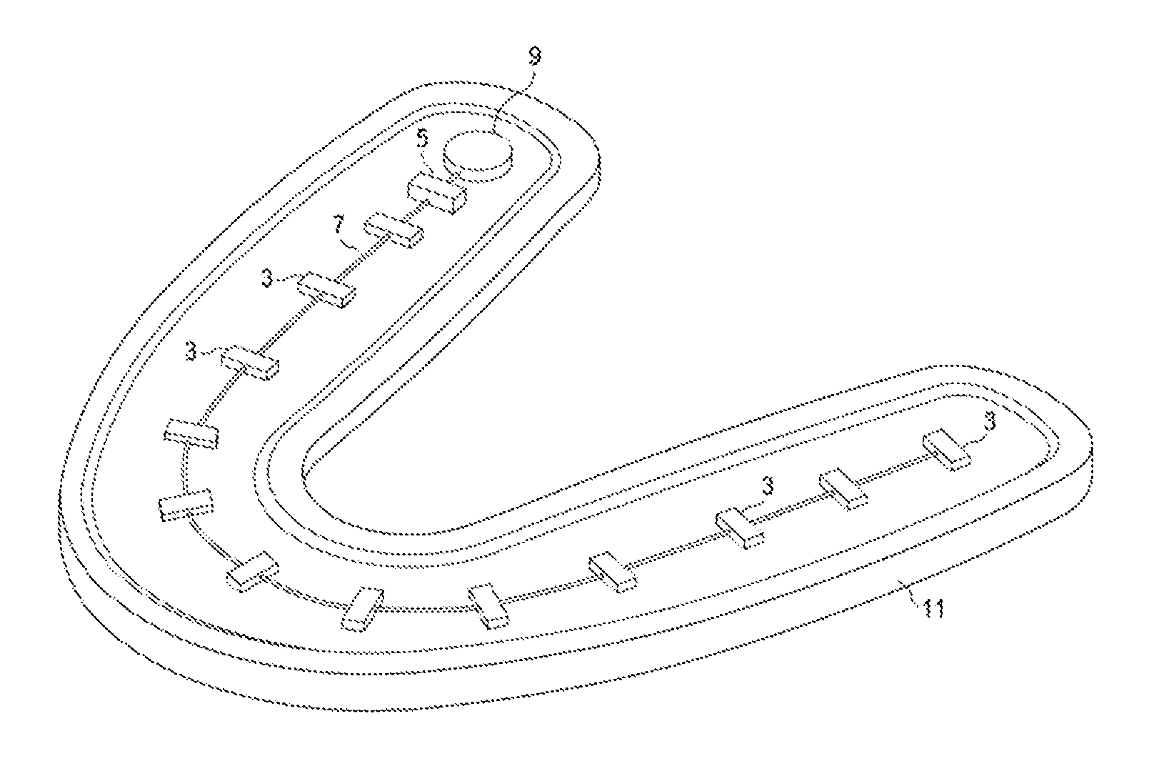
[0083]FIG. 1 shows a simple flat, U-Shaped bite plate 11 having LEDs 3 and on / off switch 5 plus wires 7 connected the LEDs 3 to the battery 9 and other components. The entirety of the bite plate 1 has a coating 11 (preferably transparent or at least IR transparent) that hermetically seals the bite plate. The user bites the plate 1, activating switch 5, so that LEDs 3 emit light, thus speeding orthodontic remodeling and reducing pain.

[0084]This simple completely intraoral embodiment can also be provided with vibrators, which can use the same or a separate on- / off switch. An separate switch may be preferred, as the time needed for light stimulation may be significantly less than the 20 minutes needed to biological response to vibration. Alternatively, a small chip embedded in the bite plate can control timing, and the same on / off switch can be used for both modes of operation.

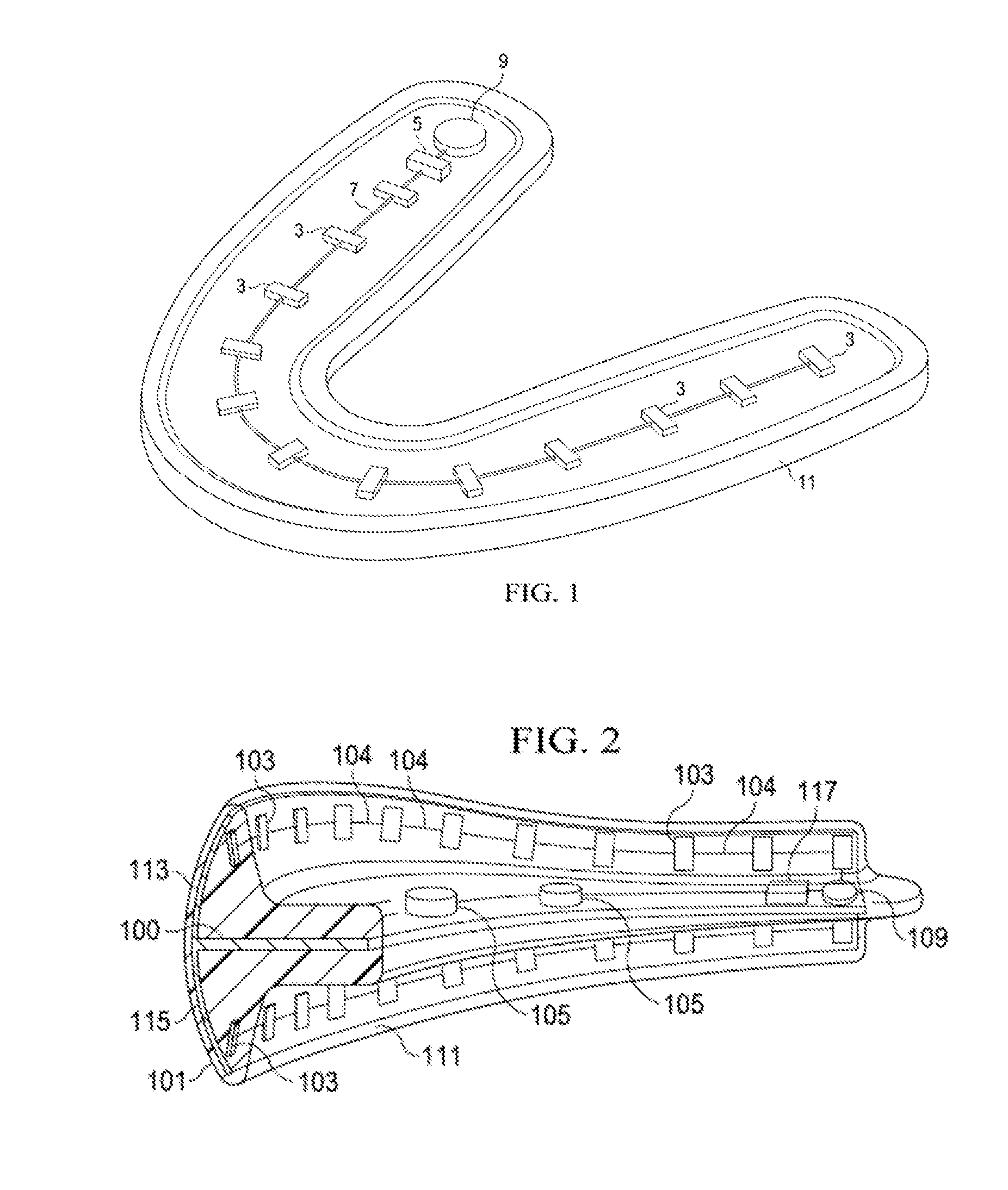
[0085]FIG. 2 shows ...


PUM


Abstract

An IR laser bite plate for orthodontic remodeling is disclosed, and the device can be combined with vibrational forces.

Description

PRIOR RELATED APPLICATIONS[0001]This application claims priority to 61 / 624,242, filed Apr. 13, 2012, and 61 / 757,288, filed Jan. 28, 2013, each incorporated herein by reference in its entirety.FEDERALLY SPONSORED RESEARCH STATEMENT[0002]Not applicable.FIELD OF THE INVENTION[0003]The invention relates to laser devices for correcting malocclusion, reducing pain, cleaning teeth, and the like.BACKGROUND OF THE INVENTION[0004]Orthodontics is a dental specialty that treats malocclusion through the movement of teeth as well as the control and modification of facial growth. This process is usually accomplished by using a continuous mechanical force to induce bone remodeling, thereby enabling the teeth to move to a better position. In this approach, orthodontic appliances provide a continuous static force to the teeth via an archwire connected to brackets affixed to each tooth or via a removable appliance such as an aligner, or some similar accessory that fits over the dentition. As the teeth...

Claims


Application Information

Patent Timeline
Patent Type & Authority Applications(United States)
IPC IPC(8): A61C7/08A61C1/00A61C7/00
CPCA61C7/08A61C1/0046A61C7/008A61C19/066
Inventor HEACOCK, GREGLOWE, MICHAEL K.
Owner ADVANCED ORTHODONTICS & EDUCATION ASSOC LLC
Why Eureka
Try Eureka