Device for the application of a transcutaneous electrical stimulation stimulus

a technology electrodes, which is applied in the field of devices for the application of transcutaneous electrical stimulation stimulus, can solve the problems of too low resistance between electrodes, detrimental to the effect of stimulation, and achieve the effect of optimal stimulation contact quality

Inactive Publication Date: 2015-06-18
CERBOMED GMBH
View PDF2 Cites 18 Cited by
  • Summary
  • Abstract
  • Description
  • Claims
  • Application Information

AI Technical Summary

Benefits of technology

[0007]Thus, it is an object of the present invention, to supply a device of the mentioned kind by which it is possible for the physician or the patient by himself in a simple manner to position the stimulation device in the ear in such a way that an optimal contact quality for the stimulation can be obtained.
[0011]Thereby, the signal elements can be light emitting diodes, wherein the light emitting diodes emit preferably light of different colour. Thereby, three light emitting diodes can be arranged. The three light emitting diodes can emit green, yellow and red light and serve as “traffic light” (see below). Also an equipment with five different coloured light emitting diodes has been proven so that it is possible to recognize the direction of the optimization in an easier manner.
[0040]Hereby, it can be of course helpful instead of a three-element display (as in the case of the classical “traffic light”) to realize a finer subdivision—as the case may be a significant finer one. This can be developed till that status that a value between “0%” and “100%” is displayed which allows more precise conclusions on the contact quality.

Problems solved by technology

A contact of the electrodes is not only optimized which causes no too high resistance between the electrodes; also, a too low resistance between the electrodes is detrimental and thus not optimal.

Method used


Image

  • Device for the application of a transcutaneous electrical stimulation stimulus
  • Device for the application of a transcutaneous electrical stimulation stimulus

Examples


Embodiment Construction

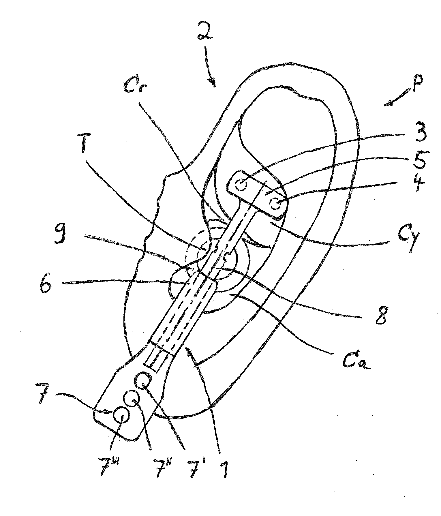
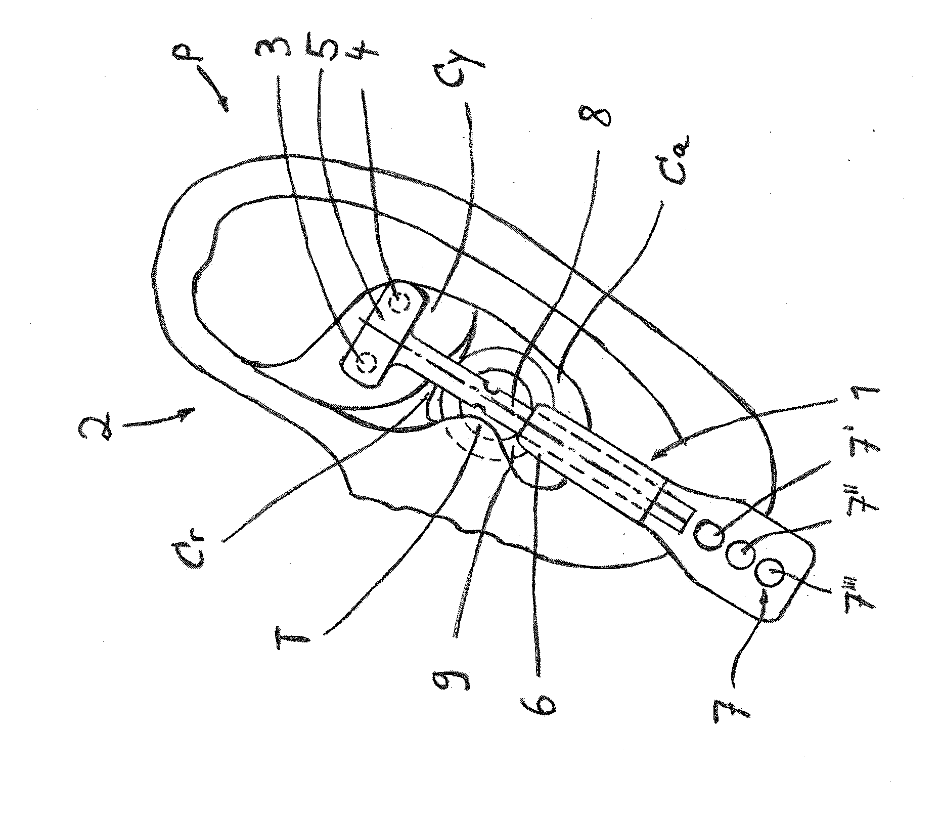
[0043]In the FIGURE a device 1 for the transcutaneous stimulation of a section of the human ear 2 is depicted. The device 1 comprises a holding rod 8 which is longitudinally movable in a base part which also comprises a controlling device 6. At the base part a resting part 9 is arranged. The general positioning of the device 1 in the ear 2 results from the indication of the substantial parts of the ear 2, namely the Pinna P with the Cavum conchae Ca, the Cymba conchae Cy, the Tragus T and the Crus helicis Cr.

[0044]At one of the ends of the holding rod 8 an electrode carrier 5 is arranged which comprises two electrodes 2 and 4 between which a potential difference is created for the purpose of a transcutaneous stimulation.

[0045]Insofar the device 1 corresponds at first to pre-known solutions, wherein especially and explicitly reference is made to DE 10 2010 054 165 B3 of the patent applicant where such a device is explained in detail.

[0046]Accordingly, the device 1 is designed to be a...


PUM


Abstract

A device for the application of a transcutaneous electric stimulation stimulus onto the surface of a section of the human ear, which includes a number of electrodes, which are arranged at or in an electrode carrier. The device includes a controlling device which controls or closed-loop controls the creation of a potential difference between the electrodes. The device has a signal device which displays or indicates the resistance which exists between the electrodes at generated potential difference when the device is arranged at or in the ear. The signal device includes at least one signal element which is switched in dependence of the measured resistance. To be able to adjust the stimulation quality of the transcutaneous stimulation by the user the device in an optimal manner the signal device has a plurality of signal elements. Different signal elements are switched in dependence on pre-determined bandwidths of the resistance.

Description

[0001]The present application claims priority of DE 10 2013 021 175.1, filed Dec. 17, 2013, the priority of this application is hereby claimed and this application is incorporated herein by reference.BACKGROUND OF THE INVENTION[0002]The invention relates to a device for the application of a transcutaneous electric stimulation stimulus onto the surface of a section of the human ear, which comprises a number of electrodes, which are arranged at or in an electrode carrier, wherein the device comprises a controlling device which controls or closed-loop controls the creation of a potential difference between the electrodes, wherein the device comprises signal means which display or indicate the resistance which exists between the electrodes at generated potential difference when the device is arranged at or in the ear, wherein the signal means comprise at least one signal element which is switched in dependence of the measured resistance.[0003]It is generally known to take influence on t...

Claims


Application Information

Patent Timeline
Patent Type & Authority Applications(United States)
IPC IPC(8): A61N1/08A61N1/36
CPCA61N1/08A61N2001/083A61N1/36014A61N1/0456A61N1/0484A61N1/3603A61N1/36036
Inventor HARTLEP, ANDREASFRENKEL, WOLF GERHARDZSCHAECK, THOMASHYCA, MARTIN
Owner CERBOMED GMBH
Why Eureka
Try Eureka