Joint, ferrule, and method for manufacturing ferrule

Active Publication Date: 2015-06-18
IHARA SCIENCE CORPORATION
View PDF14 Cites 2 Cited by
  • Summary
  • Abstract
  • Description
  • Claims
  • Application Information

AI Technical Summary

Benefits of technology

[0012]An object of the present invention is to provide a technique with which a force for driving th

Problems solved by technology

However, as opposed to a double ferrule-type fitting, where as the back ferrule 94 slides under the front ferrule 93, the front ferrule 93 rises, with point b serving as the point of effort and point d as the fulcrum, a sin

Method used


Image

  • Joint, ferrule, and method for manufacturing ferrule
  • Joint, ferrule, and method for manufacturing ferrule
  • Joint, ferrule, and method for manufacturing ferrule

Examples


Example

[0033]An example embodiment of the present invention will be described below with reference to the drawings.

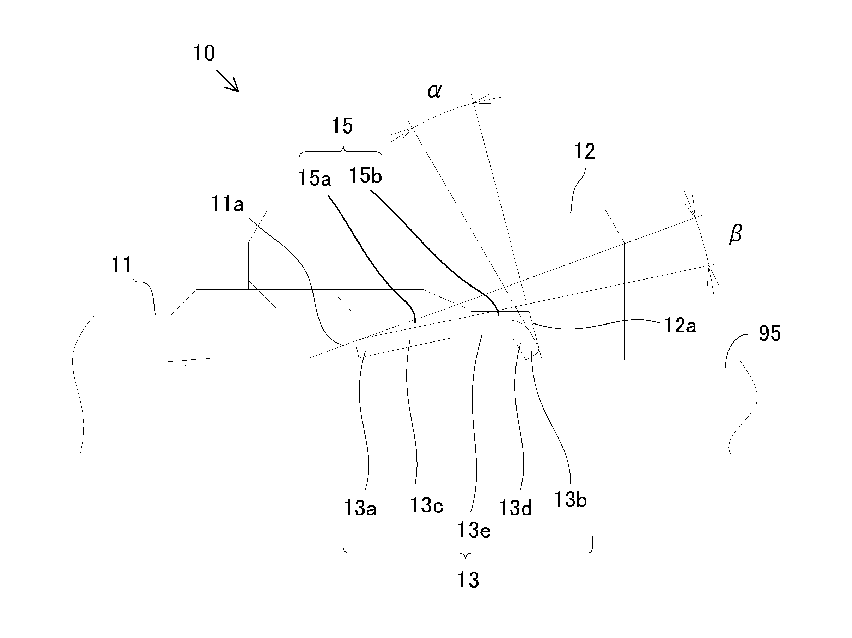
[0034]FIG. 2 is a cross-sectional view of a fitting according to the present embodiment. Referring to FIG. 2, a fitting 10 includes a fitting body 11, a nut 12, and a ferrule 13. A fitting is used connected to a pipe for purposes of connecting together pipes for passing a fluid therethrough.

[0035]The fitting body 11 and the nut 12 are coupled together by screw coupling, which can be tightened and loosened. The fitting body 11, the nut 12 and the ferrule 13 have a through hole receiving the pipe 95. The fitting 10 receives the pipe 95 through the nut 12, the ferrule 13 and the fitting body 11 in this order so that the ferrule 13 is accommodated in the accommodation space formed by the inner circumferential surface of the fitting body 11, the inner circumferential surface of the nut 12 and the outer circumferential surface of the pipe 95, and is connected to the pipe 95 as the s...


PUM

PropertyMeasurementUnit
Thicknessaaaaaaaaaa
Forceaaaaaaaaaa
Angleaaaaaaaaaa

Abstract

A fitting includes: a first member; a second member coupled by screw coupling with the first member; and a ferrule placed in an accommodation space between the first member, the second member, and a pipe. The ferrule has a rising portion including a first end portion, a pressed portion located closer to a second end portion than the rising portion, and an intermediate portion including a portion where an inner diameter is greater than the first end portion and the second end portion, the intermediate portion connecting together the rising portion and the pressed portion. The first member has a first tapered inner circumferential surface, which is an inner circumferential surface having a tapered shape, to be in contact with the first end portion of the ferrule. The second member has a pressing portion for pressing at least a portion of the pressed portion of the ferrule. The accommodation space provides a clearance for accommodating the ferrule and allowing the rising portion to rise so as to increase an angle of the rising portion.

Description

[0001]The present invention relates to a fitting for use in connection between pipes such as fluid pipes for passing fluids therethrough.BACKGROUND ART[0002]For connection between fluid pipes, a double ferrule-type fitting is a fitting that provides a high sealing property with a small tightening torque (see PTL 1 and PTL 2).[0003]FIGS. 1A to 1C are views illustrating a typical double ferrule-type fitting. Referring to FIG. 1A, a double ferrule-type fitting 90 includes a fitting body 91, a nut 92, a front ferrule 93, and a back ferrule 94.[0004]The fitting body 91 and the nut 92 are coupled together by screw coupling. As the screw coupling is tightened, the nut 92 pushes the back ferrule 94 (point a in the figure) as shown in FIG. 1A. The back ferrule 94, pushed by the nut 92, pushes the front ferrule 93 (point b in the figure) while sliding under the front ferrule 93 as shown in FIG. 1B. As the back ferrule 94 slides under the front ferrule 93, the front ferrule 93 has its tip bite...

Claims


Application Information

Patent Timeline
IPC IPC(8): F16L19/10
CPCF16L19/10B21D41/04B21D53/16Y10T29/49446
Inventor FUKAYA, SHINJIYAMAGUCHI, OSAMUMURAKAWA, TATSUYA
Owner IHARA SCIENCE CORPORATION
Why Eureka
Try Eureka