Digital broadcast signal multiplexing apparatus and digital broadcast signal multiplexing method

Inactive Publication Date: 2007-04-05
KK TOSHIBA
View PDF4 Cites 0 Cited by
  • Summary
  • Abstract
  • Description
  • Claims
  • Application Information

AI Technical Summary

Benefits of technology

[0010] In light of the above circumstances, an object of the present invention is to provide a digital broadcast signal multiplexing apparatus and a digital broadcast sig

Problems solved by technology

However, even by the technique of reducing rounding errors, calculation is complicate

Method used


Image

  • Digital broadcast signal multiplexing apparatus and digital broadcast signal multiplexing method
  • Digital broadcast signal multiplexing apparatus and digital broadcast signal multiplexing method
  • Digital broadcast signal multiplexing apparatus and digital broadcast signal multiplexing method

Examples


Example

First Embodiment

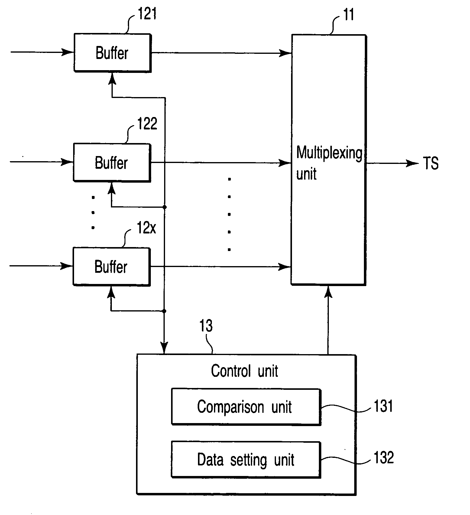
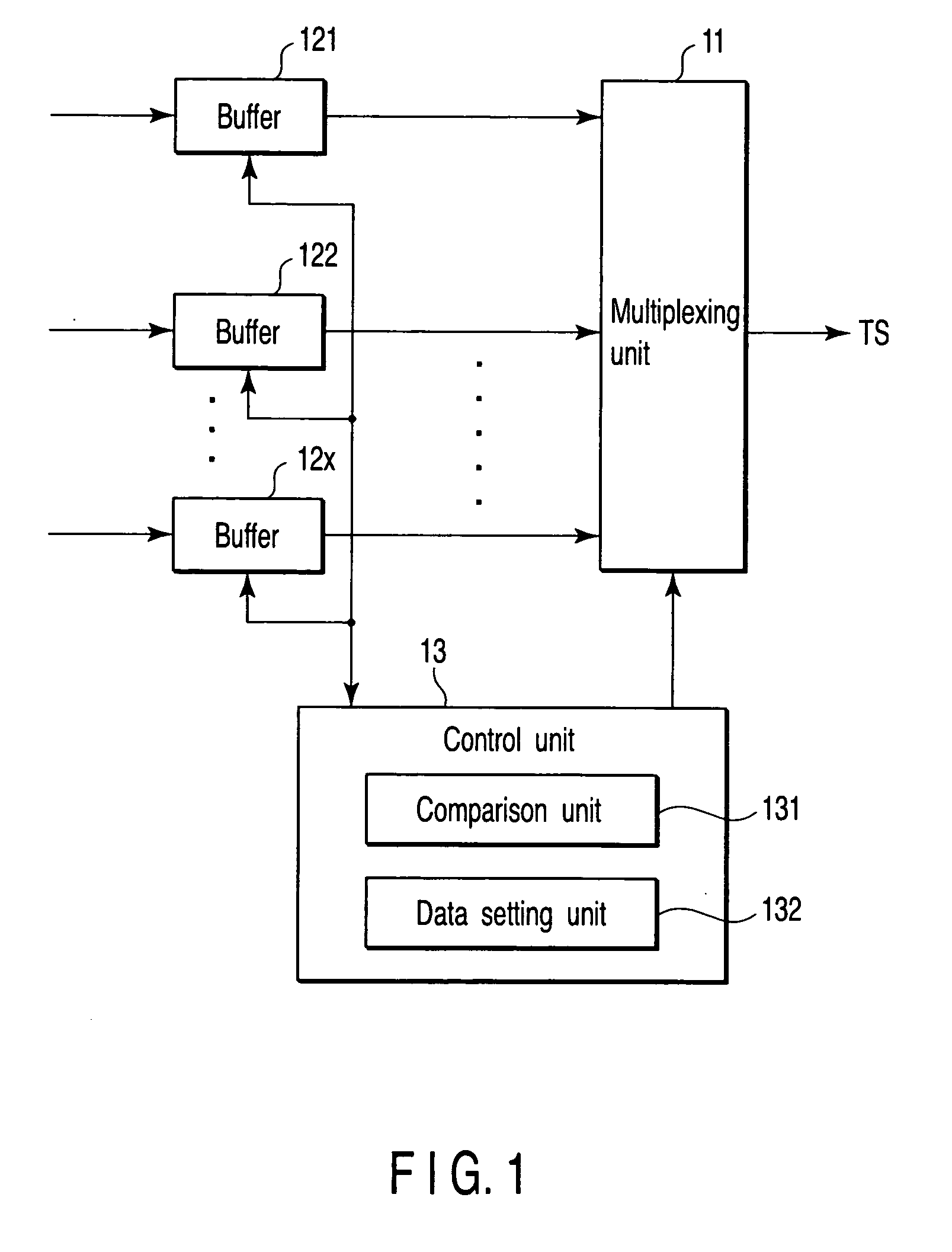
[0021]FIG. 1 is a block diagram showing a configuration of a first embodiment of a digital broadcast signal transmitting apparatus according to the present invention. In FIG. 1, reference numeral 11 is a multiplexing unit, which multiplexes TS data in accordance with the x-system MPEG2. A buffer 121 is connected to a 1st input system of the multiplexing unit 11, a buffer 122 is connected to 2nd input system, and a buffer 12x is connected up to an xth input system.

[0022] TS data of the 1st system input is stored temporarily in the buffer 121, and is then supplied to the multiplexing unit 11. In the same way, TS data of 2nd system input to xth system input are respectively stored in the buffers 122 to 12x, and then are supplied to the multiplex unit 11.

[0023] The multiplexing unit 11 is controlled to multiplex by a control unit 13, and selectively multiplexes outputs from the respective buffers 121 to 12x to transmit the outputs as TSs.

[0024] In this embodiment, a ...

Example

Second Embodiment

[0034]FIG. 4 is a flowchart showing multiple calculation processing procedures of the control unit 13 when audio data are inserted into a TS into which video data have been multiplexed, as a second embodiment of the present invention.

[0035] Here, it is supposed that the number y of TS data Y into which video data are not inserted is 7, TS data B are audio data, and the number b thereof is 4.

[0036] First, the control unit 13 sets an initial value of a cumulative sum SumY of the TS data Y in the respective buffers 121 to 12x to 0, sets an initial value of a cumulative sum SumB of the TS data B to 0, and sets m (m=n+1) to 0 (step ST4a). Then, it is determined whether or not the cumulative sum SumB is the cumulative sum SumY or more by comparing the cumulative sum SumY and the cumulative sum SumB (step ST4b). Here, because the cumulative sum SumY=0, and the cumulative sum SumB=0, the control unit 13 proceeds to step ST4c from step ST4b where the control unit 13 sets ...


PUM


Abstract

A digital broadcast signal multiplexing apparatus includes buffers store the number x of data X, a comparator determines a cumulative sum SX of the data X and a cumulative sum SA of the data A, and compares these cumulative sum SX and cumulative sum SA, a first processor sets the data A into nth data X, adds x to the cumulative sum SX when the cumulative sum SX is the cumulative sum SA, and adds a to the cumulative sum SA to determine whether or not data A is set into n+1th data X, and adds a to the cumulative sum SA to determine whether or not data A is set into n+1th data X when the cumulative sum SX is not the cumulative sum SA, a second processor causes the comparator and the first processor to repeatedly execute process until n is made to be x or more.

Description

CROSS-REFERENCE TO RELATED APPLICATIONS [0001] This application is based upon and claims the benefit of priority from prior Japanese Patent Application No. 2005-266945, filed Sep. 14, 2005, the entire contents of which are incorporated herein by reference. BACKGROUND OF THE INVENTION [0002] 1. Field of the Invention [0003] The present invention relates to a digital broadcast signal multiplexing apparatus and a digital broadcast signal multiplexing method which multiplex respective transport stream (TS) data of video and audio used for a program, for example, in accordance with the Moving Picture Experts Group 2 (MPEG2) standard. [0004] 2. Description of the Related Art [0005] In recent years, in terrestrial broadcasting systems, digital broadcasting has been started. In such digital broadcasting, respective TS data of video and audio used for a program are multiplexed and transmitted in a pattern determined in advance in accordance with the MPEG2 standard, and a broadcast program is...

Claims


Application Information

Patent Timeline
IPC IPC(8): H04N11/04H04H1/00H04H20/28H04H20/44H04J3/00H04N7/173H04N21/236H04N21/2368
CPCH04H20/28H04H60/02
Inventor HARA, KEIICHIRO
Owner KK TOSHIBA
Why Eureka
Try Eureka