Optical fiber and light source device

Active Publication Date: 2019-05-30
SUMITOMO ELECTRIC IND LTD
View PDF3 Cites 0 Cited by
  • Summary
  • Abstract
  • Description
  • Claims
  • Application Information

AI Technical Summary

Benefits of technology

[0017]According to each of the above aspects of the present invention, a dispersion-flattened highly nonlinear optical fiber can be provided that is capable of efficiently generating a wideband opti

Problems solved by technology

In optical fiber communications, such a nonlinear optical phenomenon deteriorates

Method used


Image

  • Optical fiber and light source device
  • Optical fiber and light source device
  • Optical fiber and light source device

Examples


Embodiment Construction

[0033]Embodiments of the present invention will now be described in detail with reference to the accompanying drawings, wherein like elements are denoted by identical reference numerals, and redundant description of such elements is omitted. The present invention is not limited to the following embodiments. It is intended that the scope of the present invention be defined by the appended claims and encompasses all equivalents to the claims and all changes made to the claims within the scope thereof.

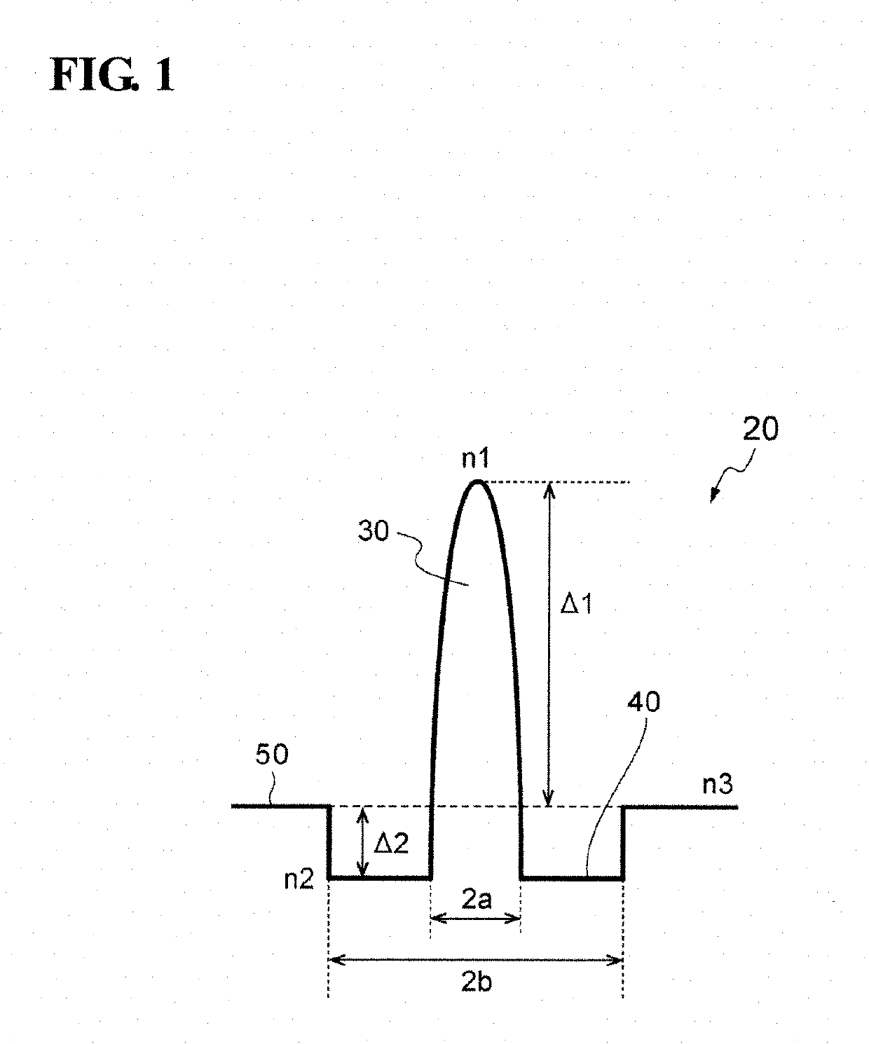
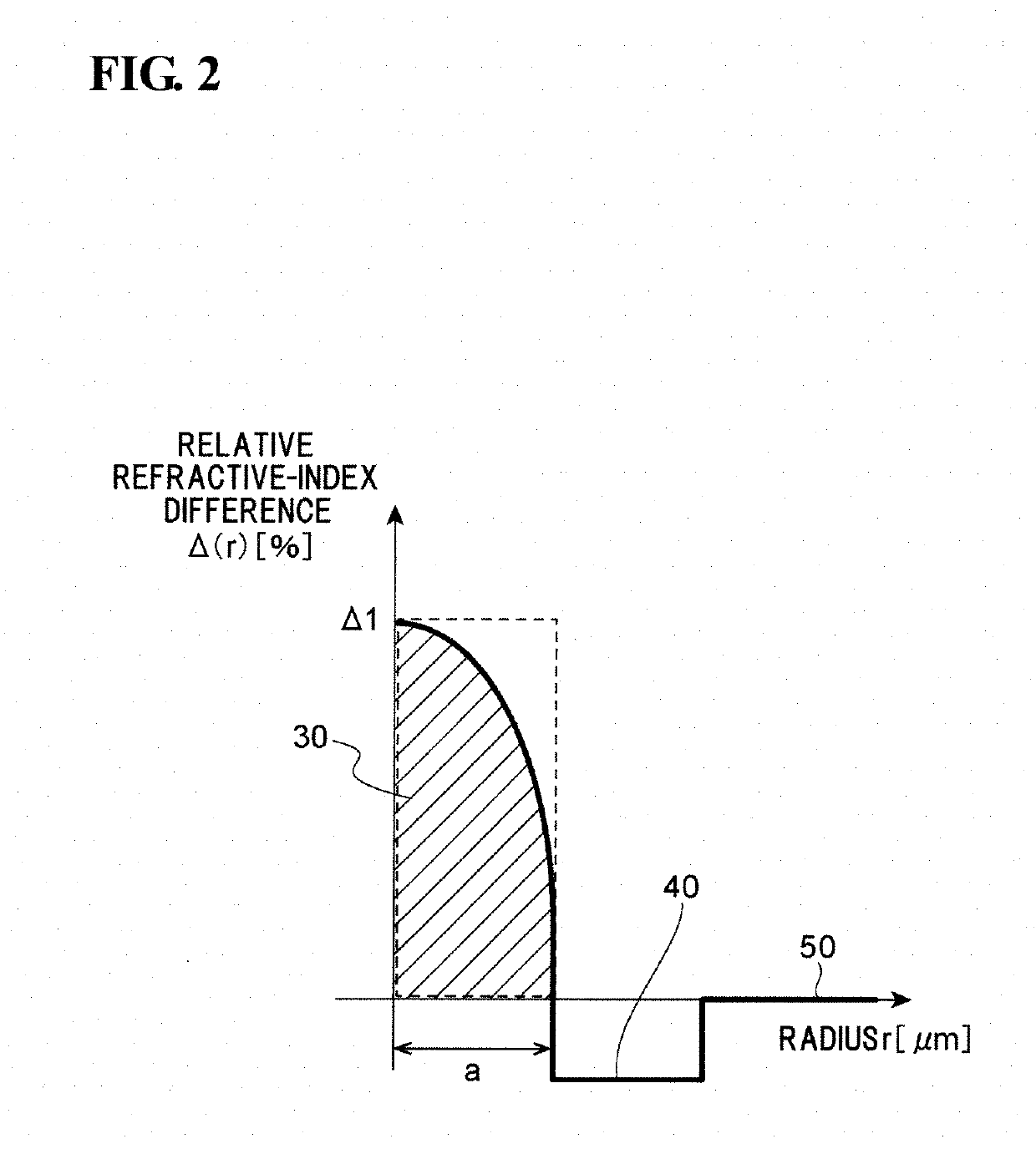
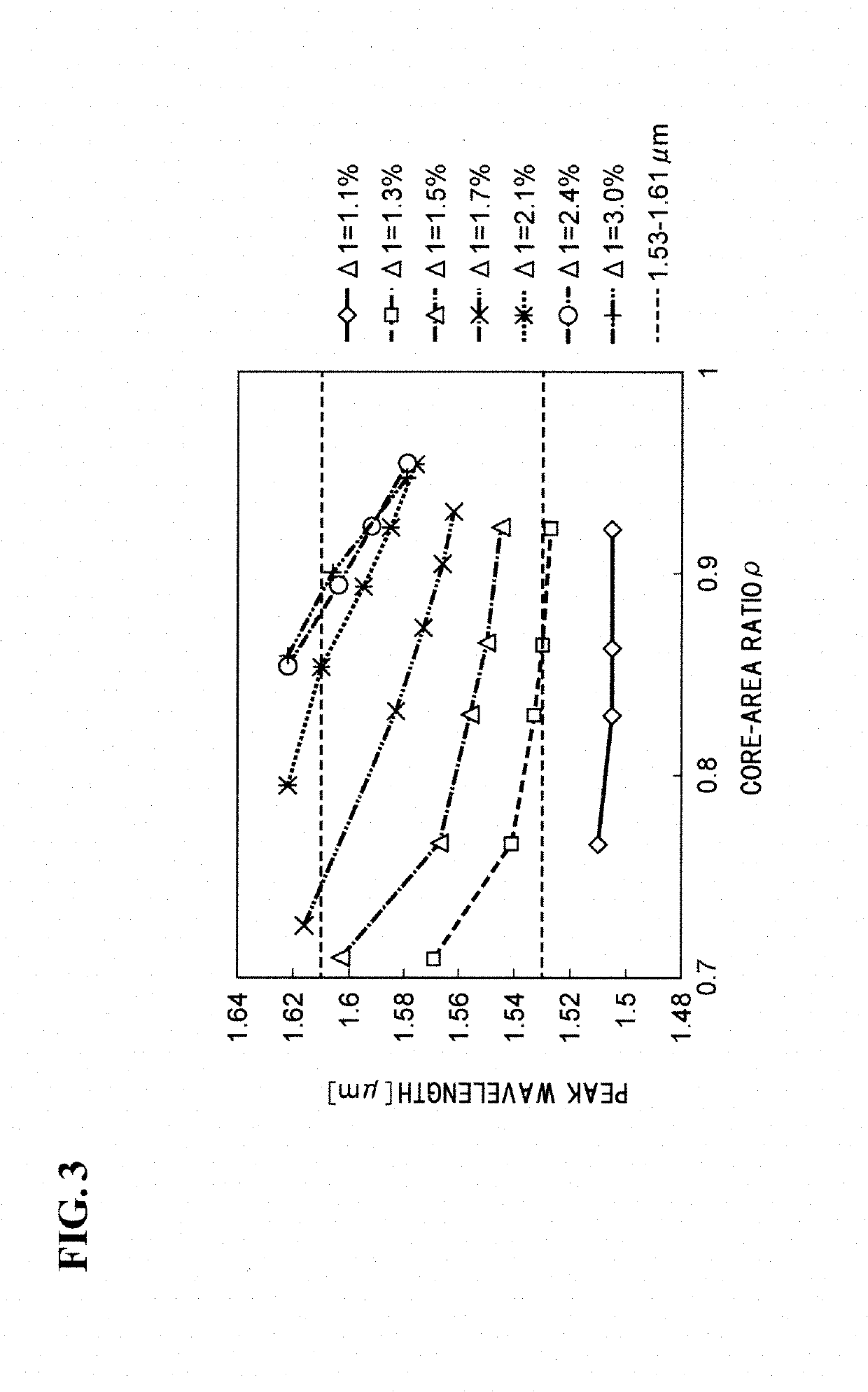
[0034]In a dispersion-flattened HNLF, as the wavelength deviates from the peak wavelength toward the shorter wavelength side or the longer wavelength side, the value of chromatic dispersion deviates from the peak dispersion. Therefore, to generate a wideband optical frequency comb over either the C band (1530 nm to 1565 nm) or the L band (1565 nm to 1610 nm) or both the C band and the L band with a small absolute value of chromatic dispersion, the peak wavelength needs to be within the C ...


PUM


Abstract

An optical fiber made of silica glass includes a core having a maximum refractive index n1, a depressed portion surrounding the core and having an average refractive index n2, and cladding surrounding the depressed portion and having an average refractive index n3. In the optical fiber, n1>n3>n2. The optical fiber has a local maximum value of chromatic dispersion within a wavelength range of 1530 nm to 1610 nm, and the local maximum value is −2 ps/nm/km or greater and below 0 ps/nm/km. (86 words)

Description

BACKGROUND OF THE INVENTIONField of the Invention[0001]The present invention relates to an optical fiber and a light source device including an optical fiber.Description of the Related Art[0002]High-power signal light propagated in an optical fiber causes a nonlinear optical phenomenon such as four-wave mixing (FWM), self-phase modulation (SPM), or cross-phase modulation (XPM). In optical fiber communications, such a nonlinear optical phenomenon deteriorates the quality of signal light and limits the capacity of information propagatable. Therefore, optical fibers for communications are desired not to cause the nonlinear optical phenomenon.[0003]Meanwhile, there has been a proposal of an applied technology in which the nonlinear optical phenomenon that occurs in an optical fiber is utilized positively. Specifically, a silica-glass-based highly nonlinear optical fiber (HNLF) has been in development as an optical fiber suitable for efficiently causing the nonlinear optical phenomenon. ...

Claims


Application Information

Patent Timeline
IPC IPC(8): G02B6/02
CPCG02B6/02038G02B6/0208G02B6/02228G02B6/02004G02B6/02G02B6/036H04B10/25G02F1/365G02B6/02028G02B6/02257G02B6/0281G02B6/03627G02F1/3528
Inventor YAMAMOTO, YOSHINORI
Owner SUMITOMO ELECTRIC IND LTD
Why Eureka
Try Eureka