A few-mode optical fiber

a technology of optical fiber and fiber optics, applied in the field of few-mode optical fiber, can solve the problems of limiting the practical application of the system, reducing the communication speed and capacity, etc., and achieve the effect of small bending radius and low splicing loss

Active Publication Date: 2018-12-27
INFORMATION & COMMNUNICATION BRANCH STATE GRID JIANGXI ELECTRIC POWER CO +2
View PDF0 Cites 0 Cited by
  • Summary
  • Abstract
  • Description
  • Claims
  • Application Information

AI Technical Summary

Benefits of technology

[0007]To solve the problem described above, therefore, a few-mode optical fiber is provided in the present invention, which is single-mode guided and remains low splicing loss at small bending radius.

Problems solved by technology

The high-order modes of the multi-mode operation will lead to serious modal dispersion for the signals propagating in the optical fibers, as a result, the communication velocity and capacity of the systems will be seriously reduced.
However, the method is rigid for connection accuracy of two ends of the few-mode optical fiber respectively to a single-mode optical fiber, which limits its practical applications.
Therefore, there is a problem to be solved to provide single-mode guided few-mode optical fibers, in which the fundamental modes have low splicing loss and small bending radius.

Method used


Image

  • A few-mode optical fiber
  • A few-mode optical fiber
  • A few-mode optical fiber

Examples


embodiment 1

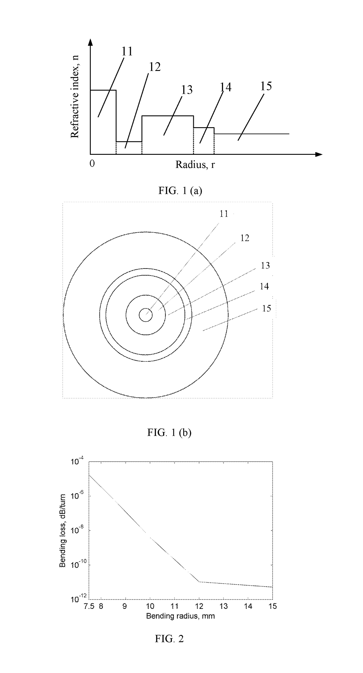
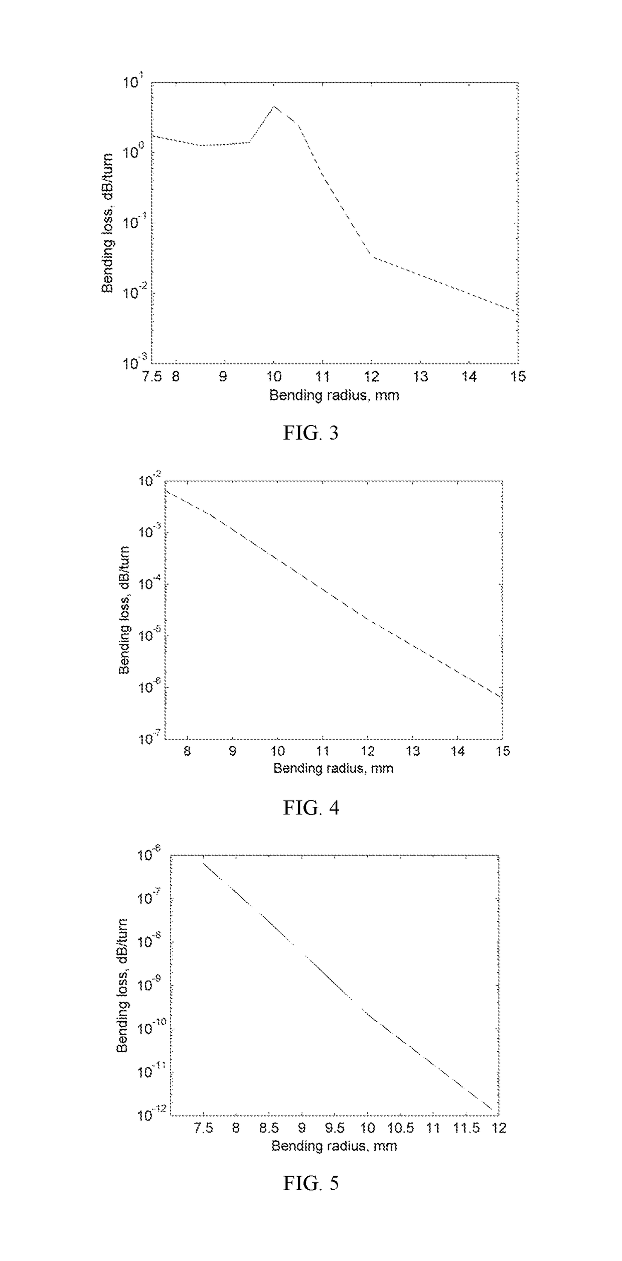
[0054]In the fiber core 11 with a core radius a1=4.4 μm, the index difference between the fiber core 11 and the downward-concave cladding layer 12 n1−n2=0.01; the index difference between the downward-concave cladding layer 12 and the first upward-convex cladding layer 13 n3−n2=0.004; and the index difference between the first upward-convex cladding layer 13 and the second upward-convex cladding layer 14 n3−n4=0.0005; the index difference between the second upward-convex cladding layer 14 and the outer cladding layer 15 n4−n5=0.0015. The radius of the downward-concave cladding layer 12, the first upward-convex cladding layer 13, and the second upward-convex cladding layer 14 fall within the following values: a2=5 μm, a3=10 μm, a4=4 μm. The mode field diameter at the wavelength of 1.310 μm is 8.8 μm. The bending loss of the LP01 mode is lower than 1×10⁻⁴ dB / turn at the bending radius of 7.5 mm. The bending loss of the LP11 mode is lower than 1.7 dB / turn at the bending radius of 10 mm...


PUM


Abstract

The refractive index of a fiber core of a few mode optical fiber is n1. A cladding layer surrounding the fiber core includes: a downward-concave cladding layer surrounding the fiber core, the refractive index thereof is n2; a first upward-convex cladding layer surrounding the downward-concave cladding layer, the refractive index thereof is n3; a second upward-convex cladding layer surrounding the first upward-convex cladding layer, the refractive index thereof is n4; an outer layer surrounding the second upward-convex cladding layer, the refractive index thereof is n5. The refractive indexes of the fiber core, the downward-concave cladding layer, the first upward-convex cladding layer, the second upward-convex cladding layer, the outer layer satisfy: n1>n3>n4>n5>n2. The fiber is a non-single mode in a direct waveguide state, and equivalent single-mode transmission can be achieved when the optical fiber is bent at a specific bending radius.

Description

BACKGROUND OF THE INVENTION1. Field of the Invention[0001]The present invention relates to an optical fiber communication technical field, and in particular to a few-mode optical fiber that provides low bending loss for the fundamental mode and is capable of achieving equivalent single-mode transmission.2. Description of Related Art[0002]With science and technology of the optical fiber communication technology widely applied to the people's daily life and work, it brought great convenience for people's daily life and work, becomes indispensable technology in people's daily life and work.[0003]Conventional single-mode optical fibers can work with moderate bending radius. However, in current daily life, the MAN (metropolitan area network), LAN (local area network), FTTH (fiber-to-the-home), and short distance communication have been popularly applied in people's daily life and work. The optical fiber should be able to work at small bending radius for flexible wiring and decreasing spa...

Claims


Application Information

Patent Timeline
Patent Type & Authority Applications(United States)
IPC IPC(8): H04B10/25G02B6/02G02B6/10G02B6/028
CPCH04B10/25G02B6/02009G02B6/10G02B6/028G02B6/03661G02B6/02047G02B6/03688G02B6/036
Inventor WANG, HUACHEN, MINGYANGYIN, PINGLI, LUMINGWEI, JINYANG, JIHAICAI, ZHIMINZHU, YUANFENGTIAN, HUI
Owner INFORMATION & COMMNUNICATION BRANCH STATE GRID JIANGXI ELECTRIC POWER CO
Why Eureka
Try Eureka