Method of splicing optical fibers with arc imagining and recentering

a technology of optical fibers and arc imagining, applied in the field of splicing optical fibers, can solve the problems of high optical loss of bad splices, insufficient temperature control to handle the situation of large distances of arc-walk, etc., and achieve the effect of low splicing loss

Inactive Publication Date: 2010-12-07
TELEFONAKTIEBOLGAT LM ERICSSON PUBL
View PDF10 Cites 0 Cited by
  • Summary
  • Abstract
  • Description
  • Claims
  • Application Information

AI Technical Summary

Benefits of technology

[0004]It is an object of the present invention to provide a method of splicing optical fibers to each other giving low splicing losses for splices made successively one after another.

Problems solved by technology

Arc-walk could result in a significant variation of the temperature distribution inside the fusion region which can in turn result in bad splices having high optical losses.
However, only temperature control is not sufficient to handle the situation of large distances of arc-walk, such as distances e.g. larger than about 30 μm.

Method used


Image

  • Method of splicing optical fibers with arc imagining and recentering
  • Method of splicing optical fibers with arc imagining and recentering
  • Method of splicing optical fibers with arc imagining and recentering

Examples


Embodiment Construction

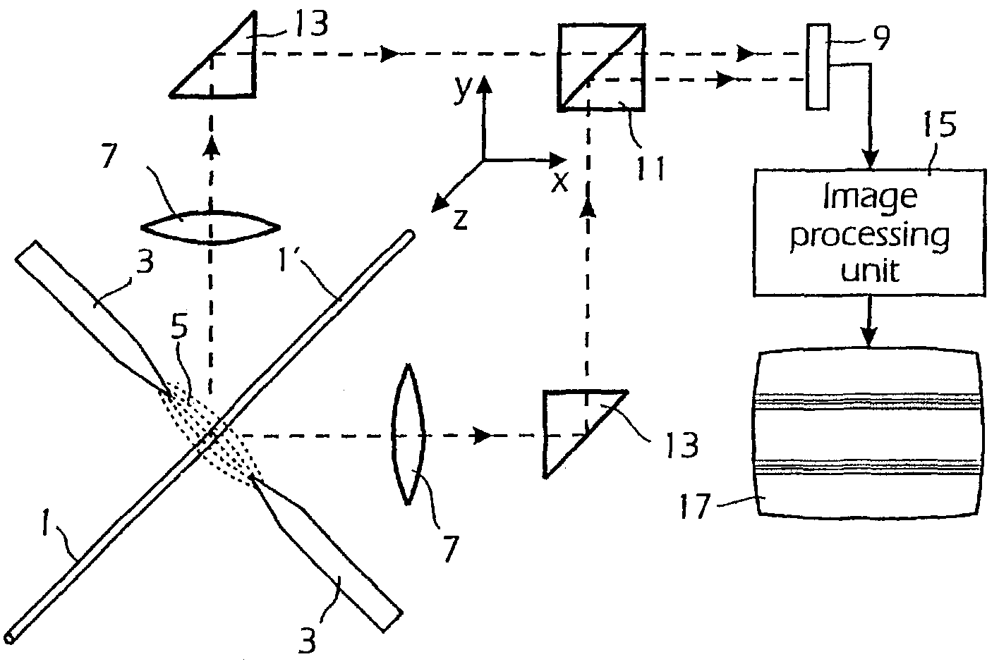
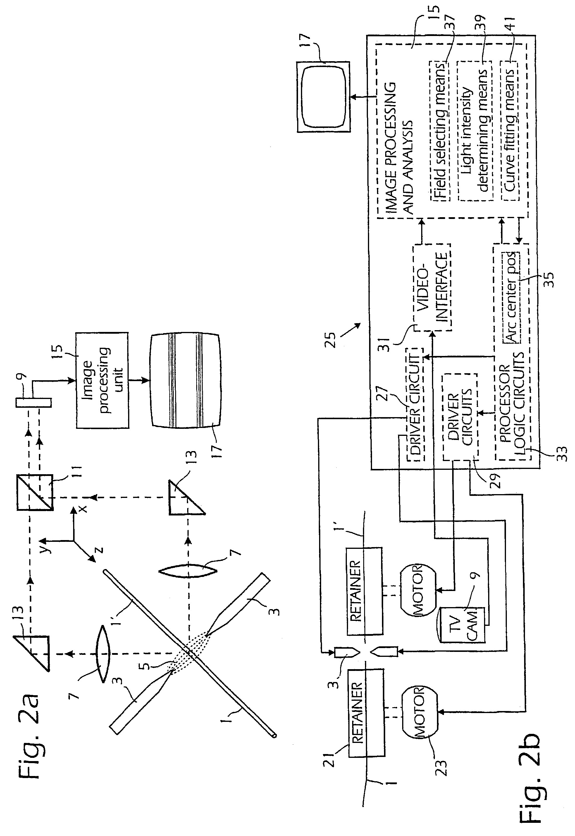
[0017]In FIG. 2a the basic setup in an automatic optical fiber splicer is shown. The fibers 1, 1′ have their end regions located between points of electrodes 3, between which an electrical discharge 5 is generated for heating the fiber ends, the intensity of the electrical discharge being controlled by the intensity of the electrical current between the electrodes 3. An optical system symbolized by lenses 7 depicts, in two perpendicular directions, the fiber end regions on the light sensitive area 9 of a camera, e.g. a plate carrying CCD elements, the light from the perpendicular directions being deflected by mirrors 11 and combined in a light combining device or beam splitter 13. In most automatic fiber fusion splicers of this type a digital imaging processing system 15 is provided for processing the electric signals from the light sensitive area9 and thereby to monitor the fibers used and the splicing procedure by controlling fiber positioning devices and the intensity of the elec...


PUM

PropertyMeasurementUnit
temperatureaaaaaaaaaa
core diameteraaaaaaaaaa

Abstract

In splicing two optical fibers to each other using an electric arc formed between electrodes images of the regions being heated and thereby fusioned to each other are taken. The images cover a rectangular field (43) having the fibers located centrally, along a center line of the field and parallel to the long sides of the field. The images are evaluated to determine a value of the position of the center of the electric arc in relation to the position of the end surfaces of the fibers. This value can then be used for placing the end surfaces just at the arc center. In the image the image of the optical fibers can be excluded so that only light intensity from the air discharge of the electric arc is recorded in the captured images. The field (41) excluded can be a narrow strip of uniform width located symmetrically around the image of the fibers. Using such a repositioning of the end surfaces of the fibers results in splices which are substantially equal to each other and thus a well repeatable splicing process is obtained.

Description

TECHNICAL FIELD[0001]The present invention relates to splicing optical fibers using the heat from an electric arc generated between two electrodes and in particular to a method of arc recentering or centering the arc, i.e. positioning the arc and end surfaces of the optical fibers to be spliced in relation to each other so that the end surfaces are placed at the center of the arc.BACKGROUND[0002]In a common type of apparatus for splicing or welding optical fibers made from basically silica or quartz to each other a high voltage applied to a pair of electrodes is used to generate an electric arc enclosing end regions of the fibers to be spliced to each other. In the electric arc the temperature is high causing material of the optical fibers inside the arc to melt and by slightly pressing the ends of the fibers to each other (this operation called “overlap”) a fusion-splice is obtained. The temperature in the fusion region must be above 1800° C. or generally about 2000° C. in order to...

Claims


Application Information

Patent Timeline
Patent Type & Authority Patents(United States)
IPC IPC(8): C03B37/07G02B6/255
CPCG02B6/2551
Inventor HUANG, WEI-PINGADEBACK, TOMASWALLIN, DAVID
Owner TELEFONAKTIEBOLGAT LM ERICSSON PUBL
Why Eureka
Try Eureka