

Catalyst for generating hydrogen and method for generating hydrogen
- Summary
- Abstract
- Description
- Claims
- Application Information
AI Technical Summary
Benefits of technology
Problems solved by technology
Method used
Image

Examples
example 1
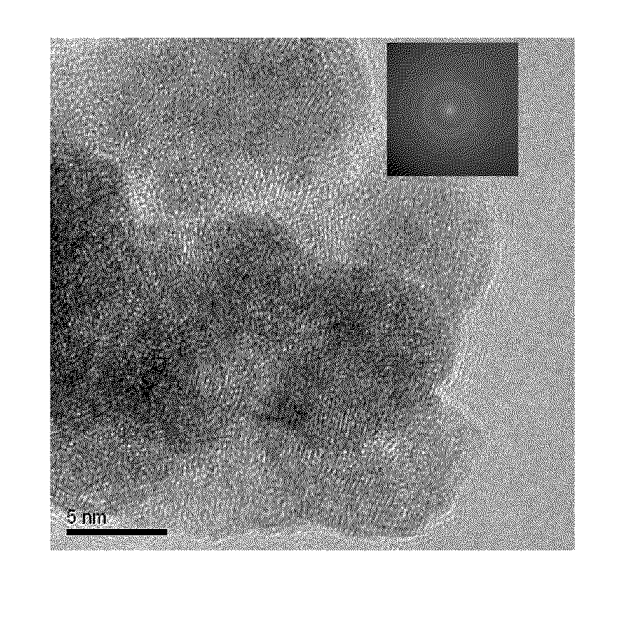
[0072]NiCl2.6H2O (0.024 g), FeSO4.7H2O (0.028 g), hexadecyltrimethylammonium bromide (CTAB, 95%) (0.100 g), and water (2.5 mL) were placed in a 30-mL two-necked flask, and the mixture was ultrasonically stirred for 5 minutes, followed by heating at 50° C. for 5 minutes. An NaBH4 (0.010 g) aqueous solution (1.5 mL) was subsequently added, and the reactor was vigorously shaken for 5 minutes, thereby forming an NiFe nanoparticle catalyst.
[0073]A transmission electron microscope (TEM) image of the NiFe nanoparticle catalyst obtained is shown in FIG. 1. As is clear from FIG. 1, the catalyst was composed of ultrafine particles having a particle size of about 10 nm.
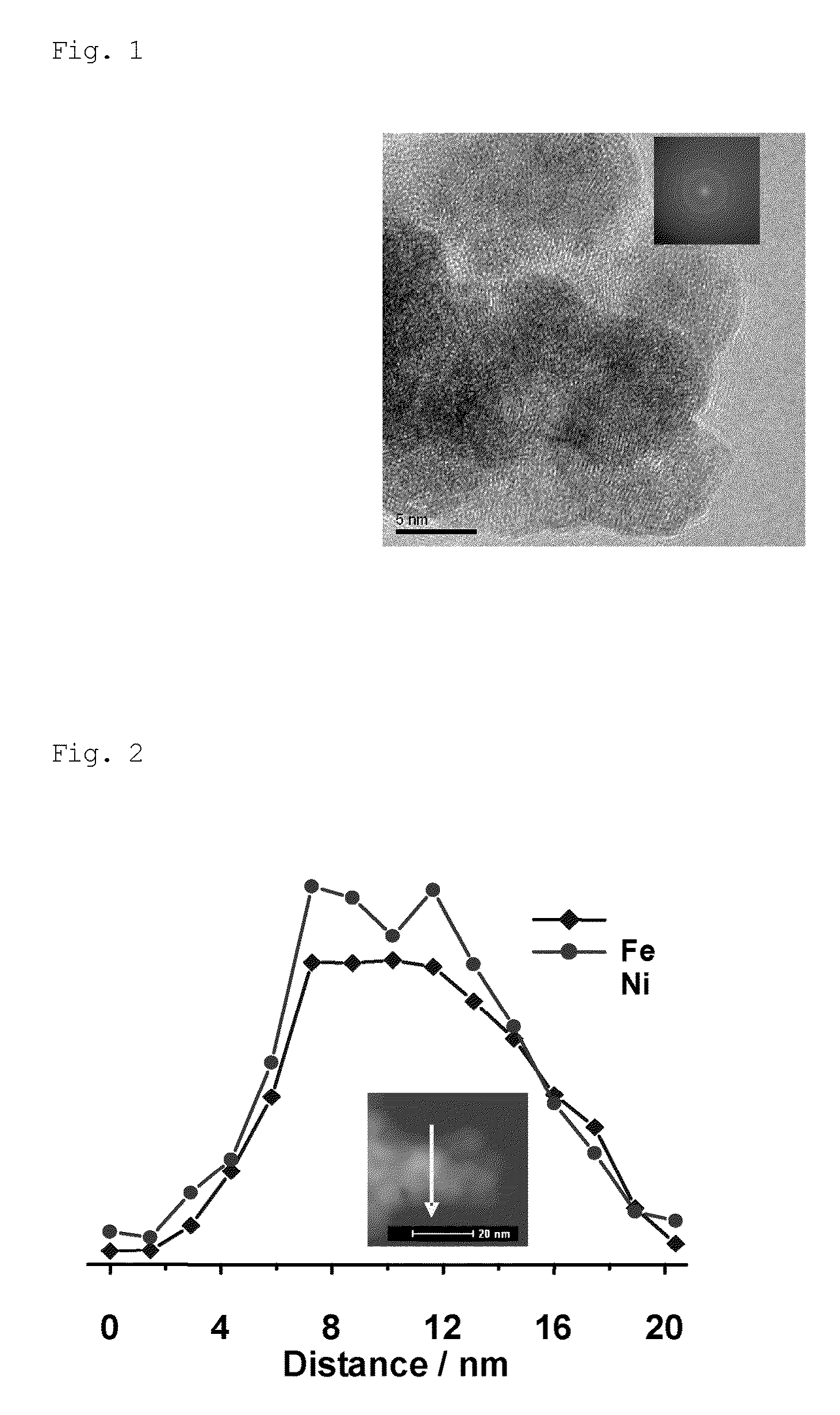
[0074]FIG. 2 shows a high-angle annular dark-field (scanning transmission electron microscope) (HAADF-STEM) image of the NiFe nanoparticle catalyst; it shows the EDS line scan spectral intensities of Fe and Ni measured along the line shown in the figure. It can be clearly seen from the EDS line scan spectra shown in FIG. 2 that ...
example 2
[0084]NiCl2.6H2O (0.024 g), FeSO4.7H2O (0.028 g), hexadecyltrimethylammonium bromide (CTAB, 95%) (0.100 g), and water (2.5 mL) were placed in a 30-mL two-necked flask, and the mixture was ultrasonically stirred for 5 minutes, followed by heating at 50° C. for 5 minutes. An NaBH4 (0.010 g) aqueous solution (1.5 mL) was subsequently added, and the reactor was vigorously shaken for 5 minutes, thereby forming an NiFe nanoparticle catalyst.
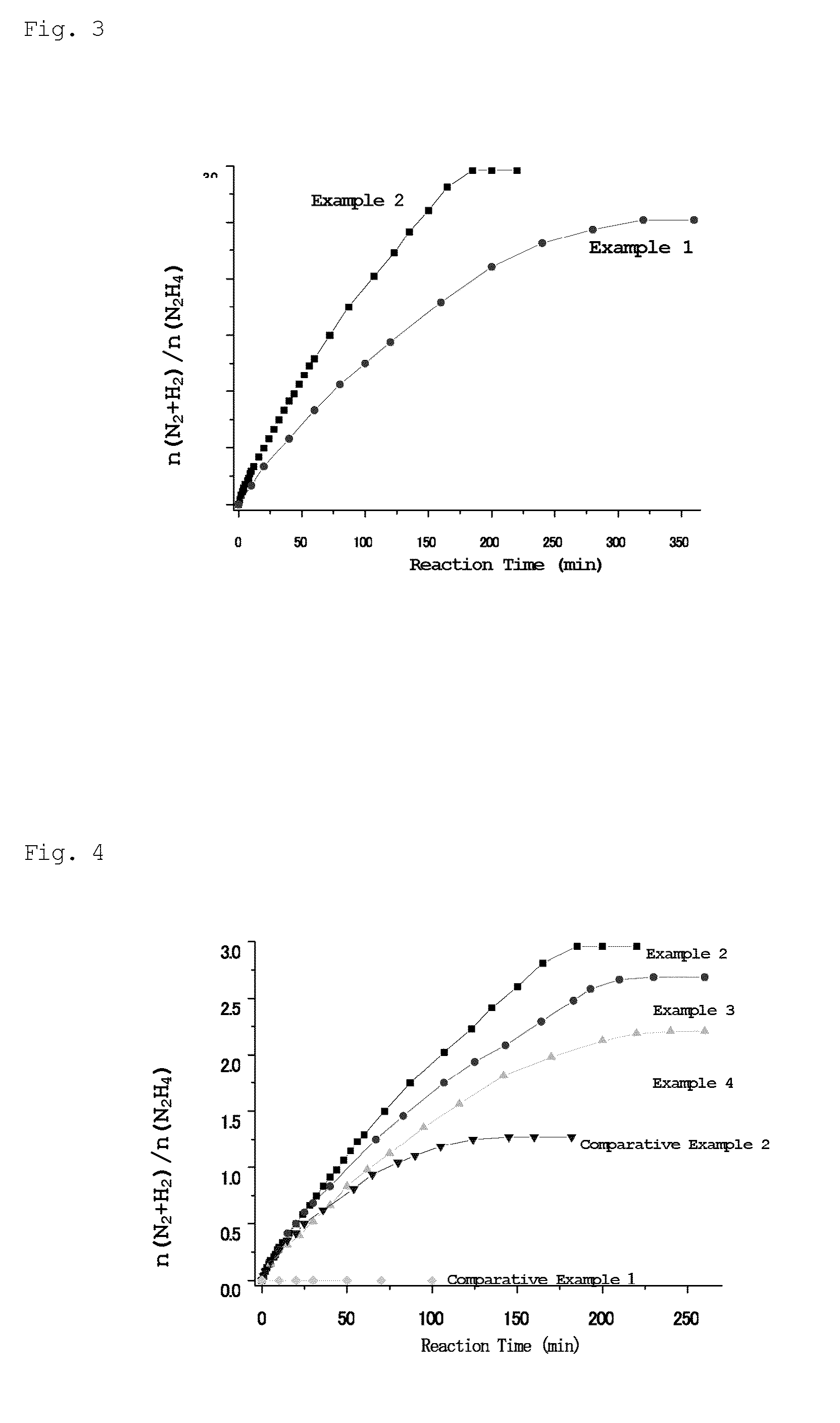
[0085]NaOH (0.080 g) was then added to the solution obtained above and the reactor was shaken to dissolve the NaOH. Hydrazine monohydrate (H2NNH2.H2O, 99%) (0.1 mL, 1.97 mmol) was added to the two-necked flask via a syringe, and stirring was continued at 70° C. Released gases were passed through a trap containing 1.0 M hydrochloric acid, where ammonia was absorbed; subsequently, only hydrogen and nitrogen were introduced into a gas burette, and the amount of the released gases was measured. After 10, 20, 32, 60, 107, 150, 185, and 220 minutes from the ...
example 3
[0089]NiCl2.6H2O (0.036 g), FeSO4.7H2O (0.014 g), hexadecyltrimethylammonium bromide (CTAB, 95%) (0.100 g), and water (2.5 mL) were placed in a 30-mL two-necked flask, and the mixture was ultrasonically stirred for 5 minutes, followed by heating at 50° C. for 5 minutes. An NaBH4 (0.010 g) aqueous solution (1.5 mL) was subsequently added, and the reactor was vigorously shaken for 5 minutes, thereby forming an Ni3Fe nanoparticle catalyst.
[0090]NaOH (0.080 g) was then added to the solution obtained above and the reactor was shaken to dissolve the NaOH. Hydrazine monohydrate (H2NNH2.H2O, 99%) (0.1 mL, 1.97 mmol) was added to the two-necked flask via a syringe, and stirring was continued at 70° C. Released gases were passed through a trap containing 1.0 M hydrochloric acid, where ammonia was absorbed; subsequently, only hydrogen and nitrogen were introduced into a gas burette, and the amount of the released gases was measured. After 5, 10, 20, 40, 83, 125, 164, and 193, 230, and 260 minu...
PUM
| Property | Measurement | Unit |
|---|---|---|
| Particle size | aaaaa | aaaaa |
| Percent by mole | aaaaa | aaaaa |
| Selectivity | aaaaa | aaaaa |
Abstract
Description
Claims
Application Information