
Shield apparatus for low-beam head lamp

a low-beam head lamp and shielding technology, which is applied in fixed installation, lighting and heating apparatus, transportation and packaging, etc., can solve the problems of reducing and not meeting the vehicle safety standards of every country. , to achieve the effect of increasing the light efficiency of the low-beam distribution area

Active Publication Date: 2015-06-18
HYUNDAI MOTOR CO LTD
View PDF2 Cites 1 Cited by
  • Summary
  • Abstract
  • Description
  • Claims
  • Application Information

AI Technical Summary

Benefits of technology

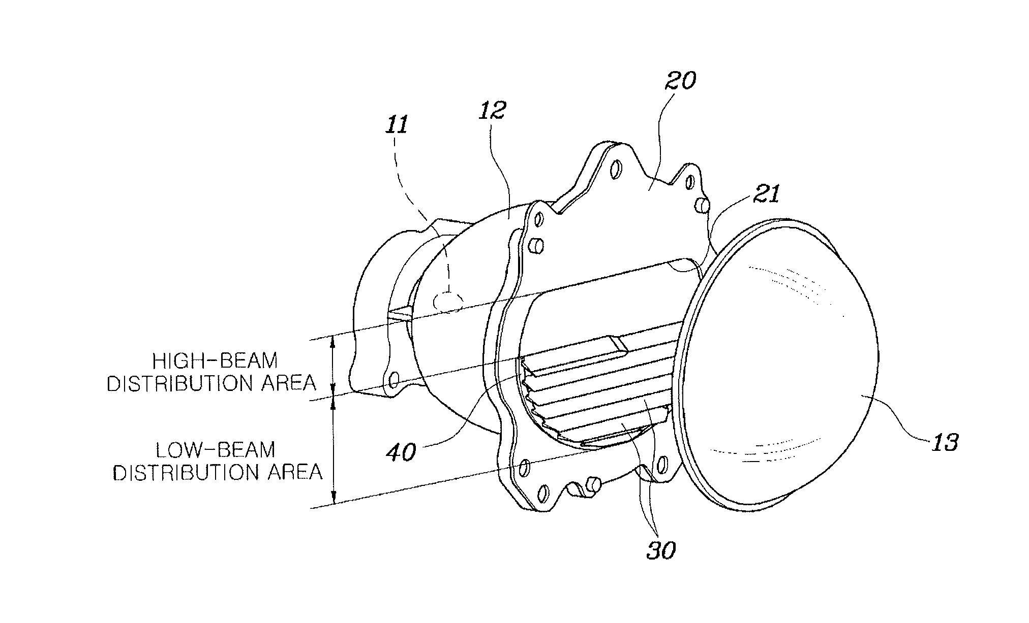
The present invention is about a shield apparatus for a low-beam head lamp that has a unique design to change the direction of light and increase its efficiency in the low-beam distribution area, which satisfies the vehicle safety standard of each country. The shield apparatus includes a plurality of blind shields that are opened at a predetermined angle, leading to a higher amount of light output. The shield apparatus also has an uppermost blind shield that prevents some of the light output from being wasted. Overall, the shield apparatus improves the brightness and efficiency of the low-beam distribution area, making it safer for drivers.

Problems solved by technology

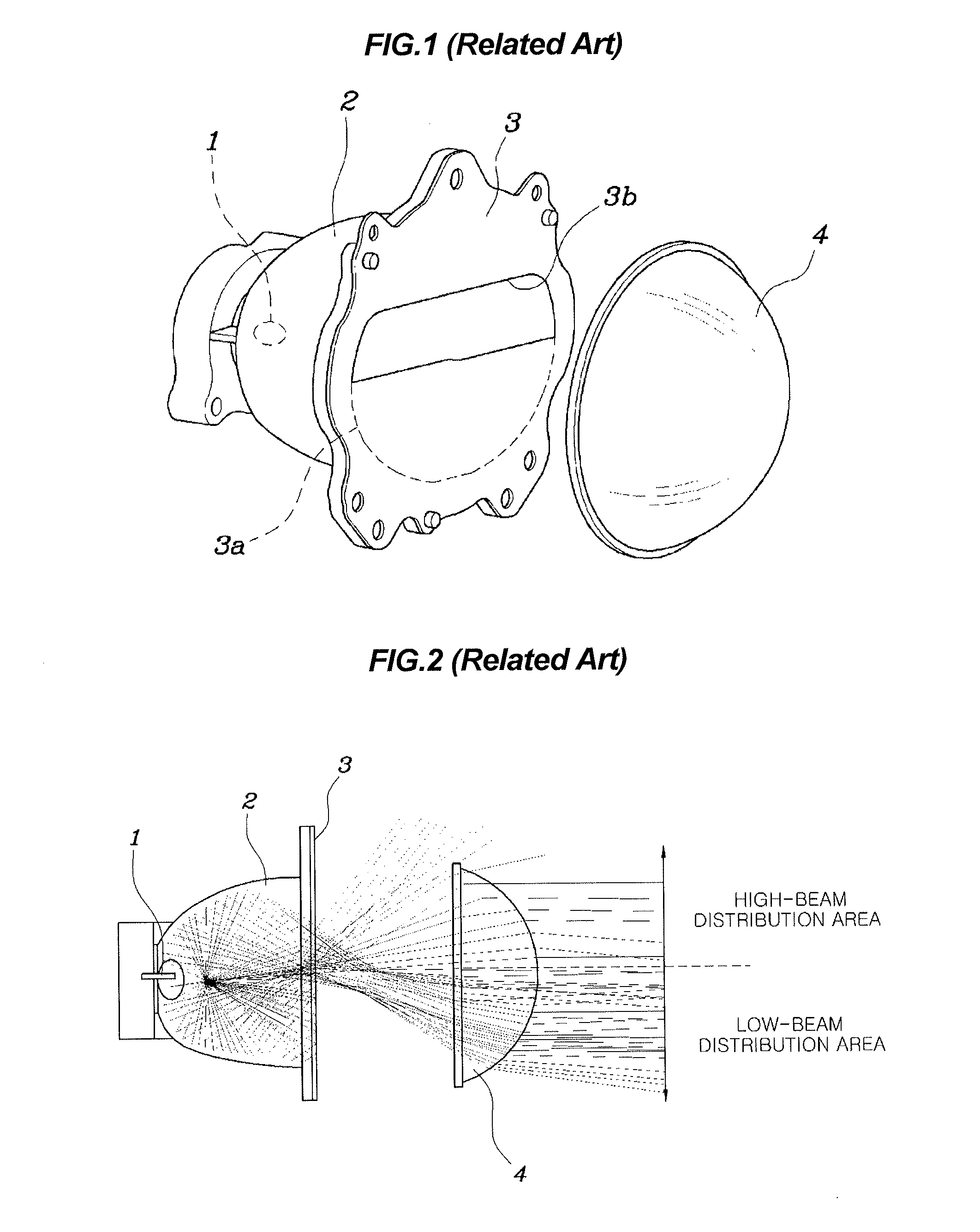
However, when the shield plate 3 having the closed low-beam distribution area 3a is used as such, some of the light outputted from the light source 1 is reflected by the projection reflector 2 and the closed low-beam distribution area 3a of the shield plate 3, and then is finally radiated to the high-beam distribution area through the through hole 3b. In this case, because of the amount of light radiated to the high-beam distribution area, the amount of light radiated to the low-beam distribution area is relatively insufficient.
Consequently, as the light efficiency of the low-beam distribution area is reduced, this does not satisfy the vehicle safety standard of every country.

Method used


Image

  • Shield apparatus for low-beam head lamp
  • Shield apparatus for low-beam head lamp
  • Shield apparatus for low-beam head lamp

Examples


Embodiment Construction

[0028]Reference will now be made in detail to various embodiments of the present invention(s), examples of which are illustrated in the accompanying drawings and described below. While the invention(s) will be described in conjunction with exemplary embodiments, it will be understood that the present description is not intended to limit the invention(s) to those exemplary embodiments. On the contrary, the invention(s) is / are intended to cover not only the exemplary embodiments, but also various alternatives, modifications, equivalents and other embodiments, which may be included within the spirit and scope of the invention as defined by the appended claims.

[0029]Hereinbelow, a shield apparatus for a low-beam head lamp according to the preferred embodiment of the present invention will be described with reference to the accompanying drawings.

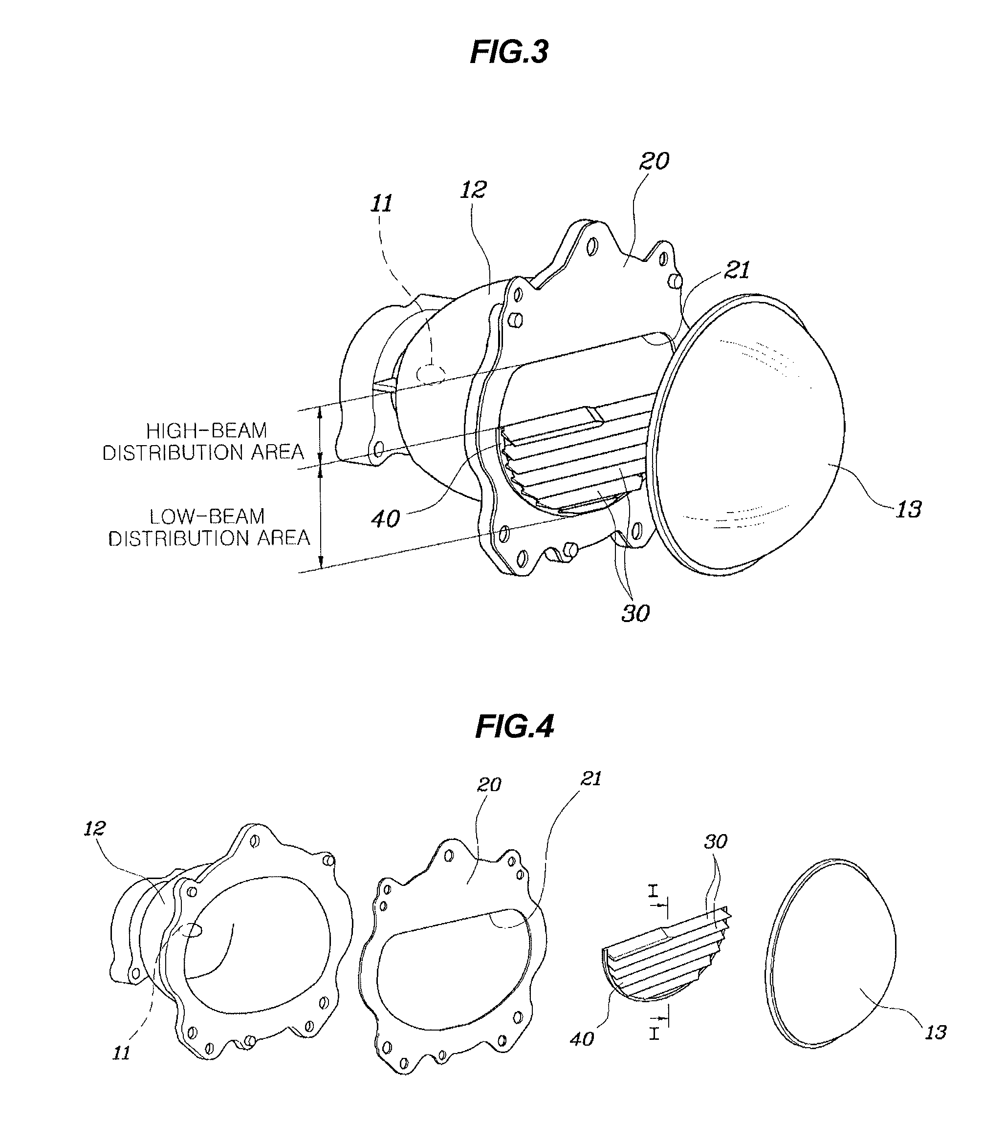
[0030]As shown in FIGS. 3 to 6, the low-beam head lamp according to an exemplary embodiment of the present invention includes a light source 11....


PUM


Abstract

A shield apparatus for a low-beam head lamp may include a projection reflector equipped with a light source therein, a shield body having a through hole being formed in the shield body towards a lens, wherein the shield body may be coupled to a front surface of the projection reflector, and wherein the through hole includes a high beam distribution area and a lower beam distribution area, and a plurality of blind shields coupled to the shield body to cover the low-beam distribution area of the through hole and arranged one above another other, wherein the blind shields may be inclined at a predetermined angle to guide an irradiation direction of light outputted from the light source towards the low-beam distribution area.

Description

CROSS REFERENCE TO RELATED APPLICATION[0001]The present application claims priority of Korean Patent Application Number 10-2013-0158792 filed on Dec. 18, 2013, the entire contents of which is incorporated herein for all purposes by this reference.BACKGROUND OF THE INVENTION[0002]1. Field of the Invention[0003]The present invention relates, in general, to shield apparatuses for low-beam head lamps, and, more particularly, to a shield apparatus for a low-beam head lamp, which includes a plurality of blind shields that are opened at a predetermined angle, thus achieving an increase in light efficiency of a low-beam distribution area.[0004]2. Description of Related Art[0005]Generally, a four-lamp projection head lamp refers to a head lamp, in which an optical module realizing a low beam and an optical module realizing a high beam are separated from each other, and two optical modules are mounted to the left and right sides of a front of a vehicle, respectively. In other words, this heat...

Claims


Application Information

Patent Timeline
Patent Type & Authority Applications(United States)
IPC IPC(8): F21S8/10
CPCF21S48/13F21S48/145F21S41/00F21S41/32F21W2102/00F21W2107/10F21S41/43B60Q1/04
Inventor LEE, SEONG HOON
Owner HYUNDAI MOTOR CO LTD
Learn More