Weight apparatus for a waveguide, probe apparatus, and method for manufacturing a weight apparatus

a waveguide and weight technology, applied in the field of measurement technology, can solve the problems of inability to meet the requirements of measurement accuracy, etc., to achieve the effect of reducing the total weight of the probe, minimising discontinuity, and improving adaptation and/or continuous transition

Active Publication Date: 2015-06-18
VEGA GRIESHABER GMBH & CO
View PDF1 Cites 12 Cited by
  • Summary
  • Abstract
  • Description
  • Claims
  • Application Information

AI Technical Summary

Benefits of technology

The present invention relates to a cable probe apparatus that can determine the end of the cable by provoking strong reflections. The weight body of the cable probe is made of a material that matches the material of the waveguide to reduce interference and reflective reflections. Furthermore, the probe apparatus includes a dielectric core that can be surrounded with conductive material to reduce the overall weight of the probe and tighten the probe at the end. The technical effect of the invention is to improve the accuracy and precision of cable probe measurements.

Problems solved by technology

However, the tightening weights used for the tightening may themselves influence the measurement results.

Method used


Image

  • Weight apparatus for a waveguide, probe apparatus, and method for manufacturing a weight apparatus
  • Weight apparatus for a waveguide, probe apparatus, and method for manufacturing a weight apparatus
  • Weight apparatus for a waveguide, probe apparatus, and method for manufacturing a weight apparatus

Examples


Embodiment Construction

[0057]The illustrations in the drawings are schematic and not to scale. In the following description of FIG. 1 to FIG. 12, like reference numerals are used for like or corresponding elements.

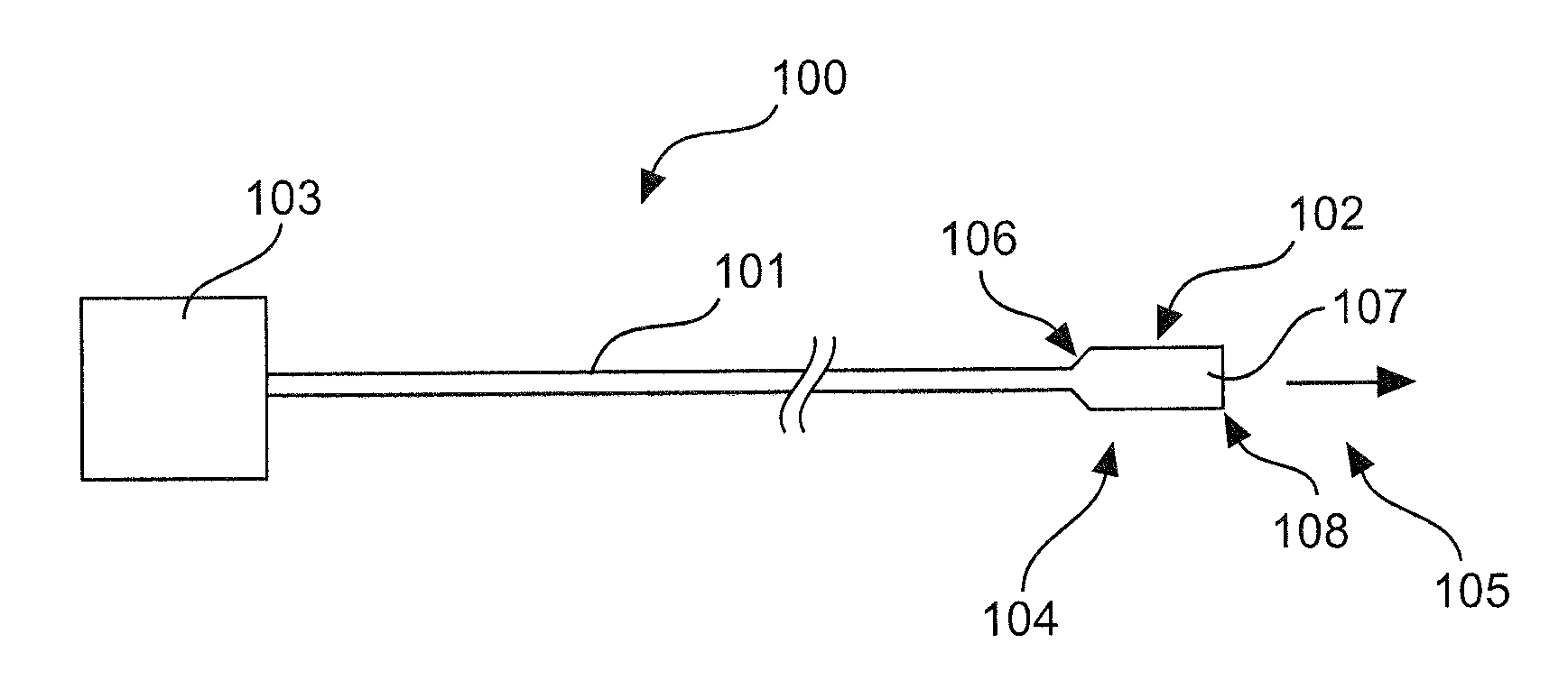
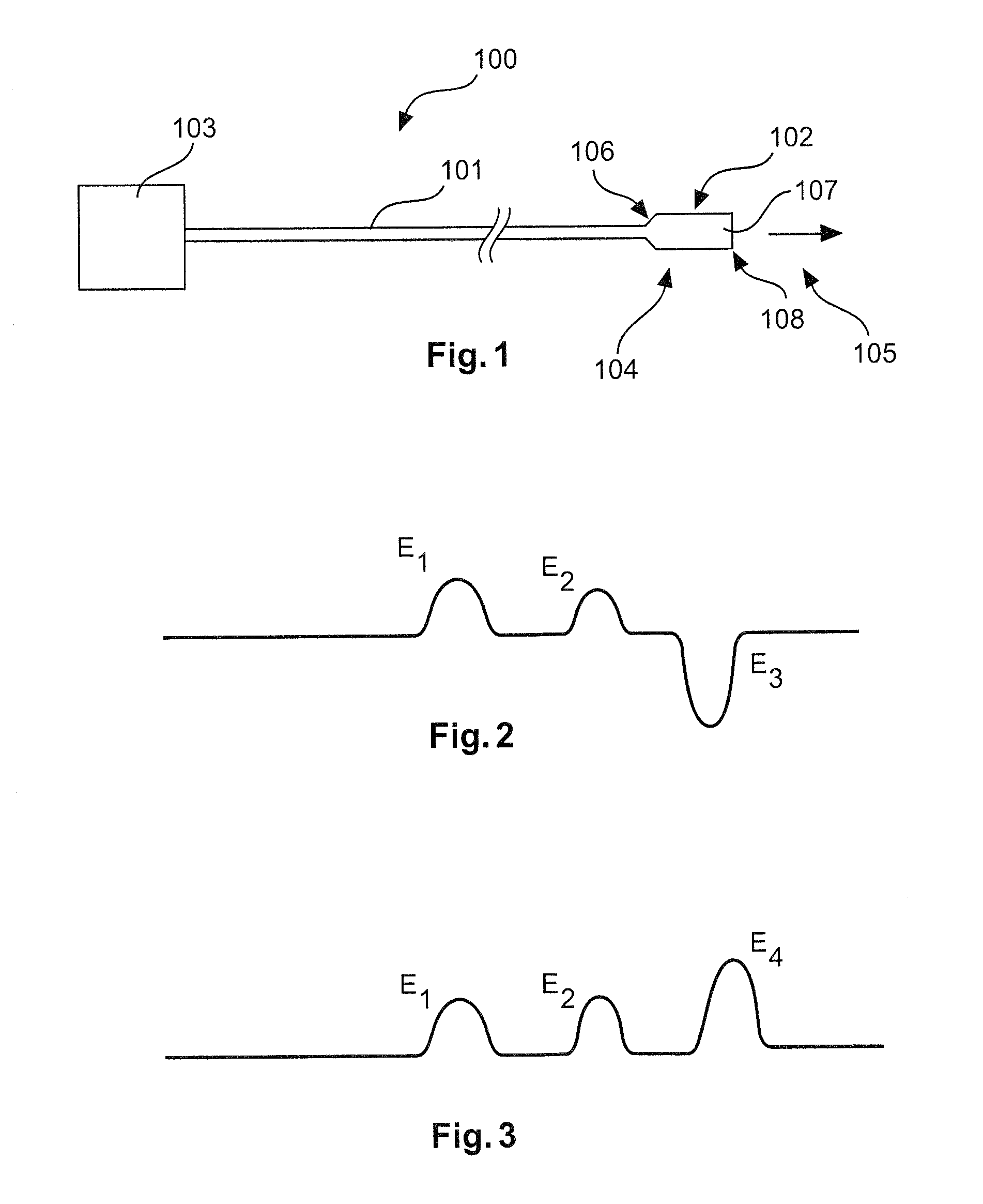
[0058]FIG. 1 shows a probe apparatus 100, which comprises a waveguide 101 and a weight apparatus 102 in the form of a tightening weight 102, for better understanding of the present invention. The waveguide 101 is formed as a cable 101 or wire cable 101. FIG. 1 shows a measurement arrangement consisting of a TDR sensor 103 and the probe apparatus 100. The TDR sensor 103 may be formed as a generator for electromagnetic, optical, acoustic or thermal waves. Accordingly, the probe apparatus 100 may be formed for transporting the associated waves. Without loss of generality, it may be assumed that the TDR sensor 103 produces electromagnetic waves which move along the cable 101 towards the tightening weight 102. The electromagnetic waves may be continuous or pulsed waves.

[0059]In the present text, the ...


PUM

PropertyMeasurementUnit
diametersaaaaaaaaaa
diametersaaaaaaaaaa
diametersaaaaaaaaaa

Abstract

A weight apparatus for a waveguide has a wave resistance. The weight apparatus includes a weight body having a fixing device. The fixing device is adapted to fix the weight body to the waveguide and has a wave resistance which is substantially adapted to the wave resistance of the waveguide.

Description

REFERENCE TO RELATED APPLICATIONS[0001]This application claims the benefit of the filing date of European Patent Application Serial No. 13 197 494 filed on 16 Dec. 2013, the disclosure of which is hereby incorporated herein by reference.TECHNICAL FIELD[0002]The present invention relates to the technical field of measurement technology. In particular, the present invention relates to a weight apparatus, to a probe apparatus, to a method for manufacturing a weight apparatus and to a level measuring instrument.BACKGROUND OF THE INVENTION[0003]Fill levels can be measured by evaluating reflections or echoes of guided microwaves or guided radar waves. For this purpose, waves or signals propagate along a probe within a container and are reflected when they come into contact with a filling material or with air. These reflections can be identified as echoes in an echo diagram. By surveying the intervals of the echoes obtained during this measurement, the fill level within the container can b...

Claims


Application Information

Patent Timeline
Patent Type & Authority Applications(United States)
IPC IPC(8): G01F23/284H01P11/00
CPCH01P11/00G01F23/284Y10T29/49016G01F23/288G01F23/292
Inventor HAAS, JUERGENHOFERER, CHRISTIANGRIESSBAUM, KARL
Owner VEGA GRIESHABER GMBH & CO
Why Eureka
Try Eureka