Single crystal turbine blade lifing process and system

a single crystal turbine and blade technology, applied in the direction of machines/engines, instruments, and mechanical means, can solve the problems of turbine blade fatigue damage, turbine components including turbine blades, and vibration

Inactive Publication Date: 2015-06-18
SOLAR TURBINES
View PDF3 Cites 8 Cited by
  • Summary
  • Abstract
  • Description
  • Claims
  • Application Information

AI Technical Summary

Problems solved by technology

The extreme operating conditions of the turbine section result in creep and fatigue damage to the turbine components including the turbine blades.

Method used


Image

  • Single crystal turbine blade lifing process and system
  • Single crystal turbine blade lifing process and system
  • Single crystal turbine blade lifing process and system

Examples


Embodiment Construction

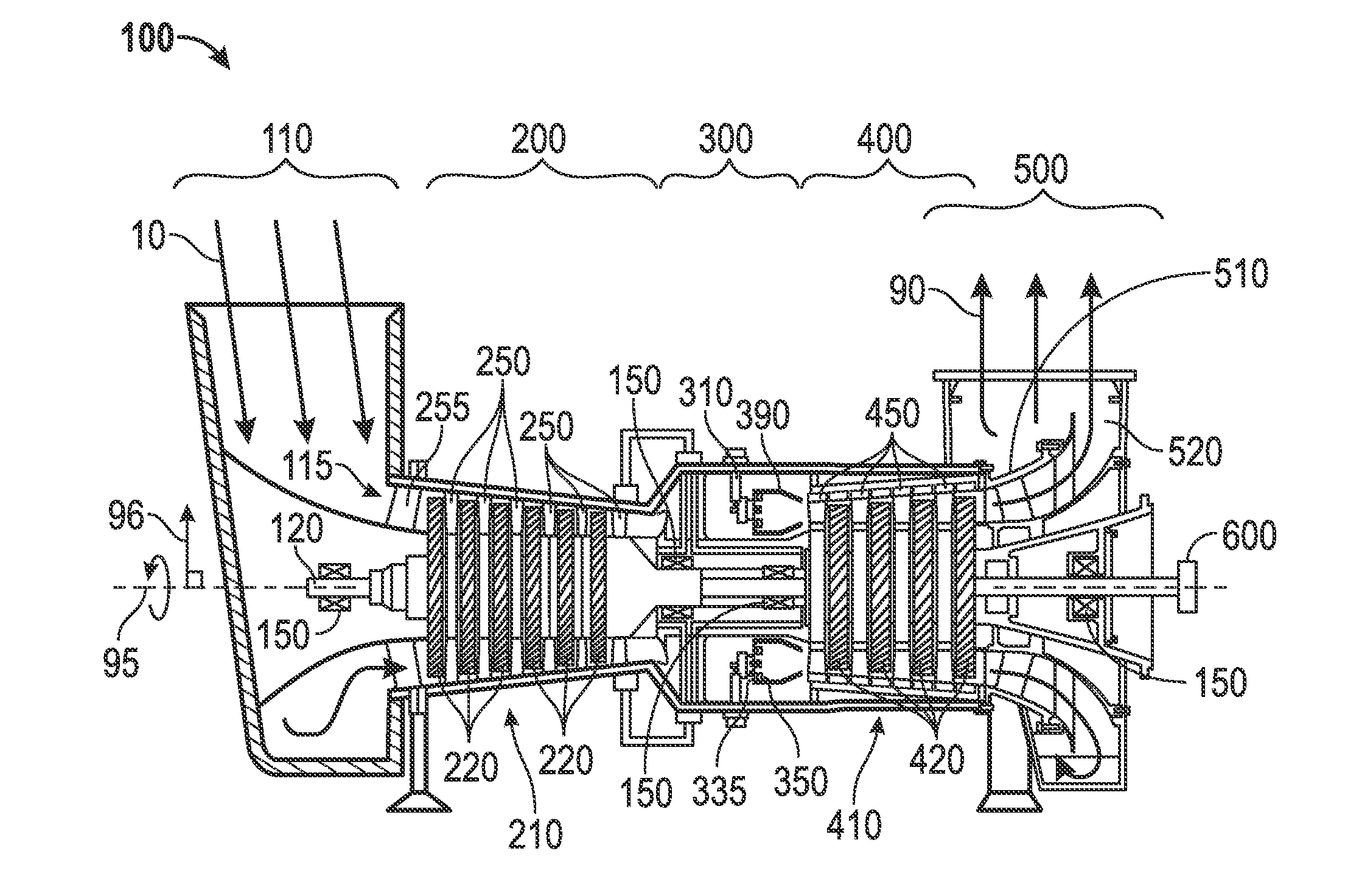
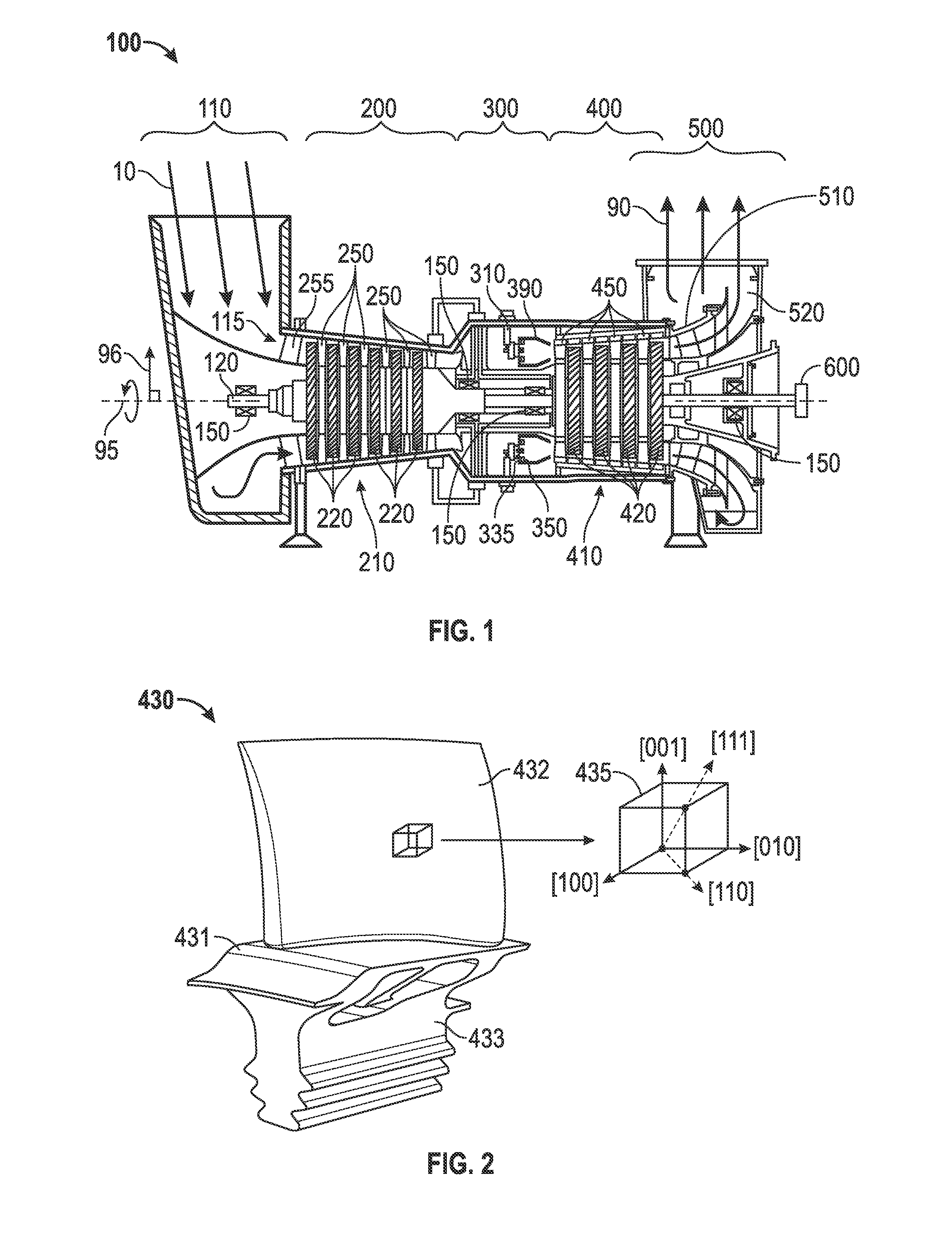
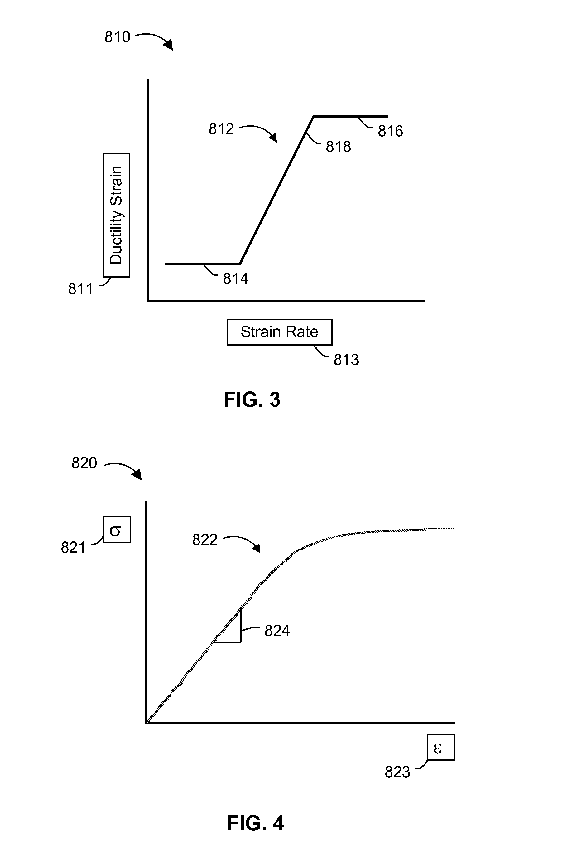
[0018]The systems and methods disclosed herein include a gas turbine engine and a system for lifing single crystal turbine blades of the gas turbine engine. The systems and methods use a ductility exhaustion approach to combine the damaging effects of creep and fatigue. Ductility exhaustion is based on strain rate of both the plastic response during a transient portion of the load cycle, defined as the cyclic or fatigue component and the strain rate from the viscoplastic response during the dwell portion of the load cycle or creep component. The systems and methods use the fatigue and creep stresses determined in an orthotropic manner and convert them into anisotropic stresses and strains by resolving the stresses determined in an orthotropic manner into the shear stresses on the primary slip planes. The shear stresses are then used to determine the anisotropic fatigue and creep strains and strain rates for the single crystal turbine blade. The strain rate for the single crystal tur...


PUM


Abstract

A system and methods for lifing a single crystal turbine blade of a gas turbine engine is disclosed. The system and methods determine the anisotropic strain of the single crystal turbine blade caused by fatigue and creep by resolving the shear stresses on each of the primary slip systems of the single crystal turbine blade. The system and methods use a ductility exhaustion method to combine the anisotropic fatigue and creep strains to determine the operating life of the single crystal turbine blade.

Description

TECHNICAL FIELD[0001]The present disclosure generally pertains to gas turbine engines, and is more particularly directed toward a lifing process and system for single crystal turbine blades of a gas turbine engine.BACKGROUND[0002]Gas turbine engines include an inlet, a compressor section, a combustor section, a turbine section, and an exhaust. The extreme operating conditions of the turbine section result in creep and fatigue damage to the turbine components including the turbine blades. Processes and systems for determining the life of turbine components are used to predict when the turbine components might fail so that the turbine components can be replaced prior to failure.[0003]U.S. Pat. No. 7,162,373 to Y. Kadioglu is directed to a method for predicting a remaining operational life of a turbine component including: obtaining crack flaw data regarding current crack flaws in the turbine component; using the crack flaw data with data regarding the structure and operating condition...

Claims


Application Information

Patent Timeline
Patent Type & Authority Applications(United States)
IPC IPC(8): G01M15/14
CPCG01M15/14F05D2260/82F01D5/28F05D2300/607
Inventor GREEN, RICHARD JAMESDOUGLAS, JONATHAN PAUL
Owner SOLAR TURBINES
Why Eureka
Try Eureka