Multiple LP-mode fiber designs for mode-division multiplexing
a technology of optical fiber and multiplexing mode, which is applied in the direction of optical fibre with graded refractive index core/cladding, optical waveguide light guide, instruments, etc., can solve the problems of undesired modes being absorbed into the outer cladding, and achieve the effect of reducing rayleigh scattering, reducing attenuation losses, and achieving transmission properties
- Summary
- Abstract
- Description
- Claims
- Application Information
AI Technical Summary
Benefits of technology
Problems solved by technology
Method used
Image
Examples
example 1
[0102]FIG. 11 shows a raised-triangle profile based on actual VAD core shape. The fiber has 116 ps / km DGD at 1550nm for the LP01, LP11, LP02, and LP21 modes.
[0103]The following chart gives calculated properties of the raised-triangle, depressed-clad profile shown in FIG. 11:
dgdnwavegd01gd11gd02gd03gd12gd21(ps / m)N01N11N02N03N12N211.304890.34890.04891.74886.74890.75.0441.451141.449901.4487701.447371.448711.314890.34890.04891.74886.14890.75.5561.451021.449771.4486301.447221.448571.324890.34890.04891.74885.54890.76.1501.450901.449641.4484801.447081.448431.334890.44890.14891.74884.74890.76.9801.450781.449511.4483401.446941.448281.344890.44890.14891.74890.81.5941.450651.449371.44819001.448141.354890.44890.24891.74890.81.5541.450531.449241.44805001.448001.364890.54890.24891.84890.81.5121.450411.449111.44791001.447861.374890.64890.34891.84890.91.4661.450281.448981.44776001.447711.384890.64890.44891.84891.01.4181.450161.448851.44762001.447571.394890.74890.54891.84891.01.3661.450041.448711.44...
example 2
[0107]FIG. 12 shows a refractive index profile for Example 2. The fiber has a GRIN core a shelf and a trench. This profile describes a generic class of optical fibers that are particularly effective for multiple mode multiplexing. Profile parameters for the fiber design, describing the core, shelf, trench, are:
index regionstart deltaend deltaalphawidth (μm)10.008000.001131.97210.0020.000000.000000.0001.923−0.00410−0.004100.0003.2840.000000.000000.00050.30
1550 nm propertiesLP01LP11LP02LP21chromatic dispersion18.919.319.119.4(ps / nm·km)effective area Aeff (μm2)93.293.5186.9124.6effective index difference0.00810.00530.00250.0025
[0108]FIG. 13 shows the differential group delays for the optical fiber of Example 2.
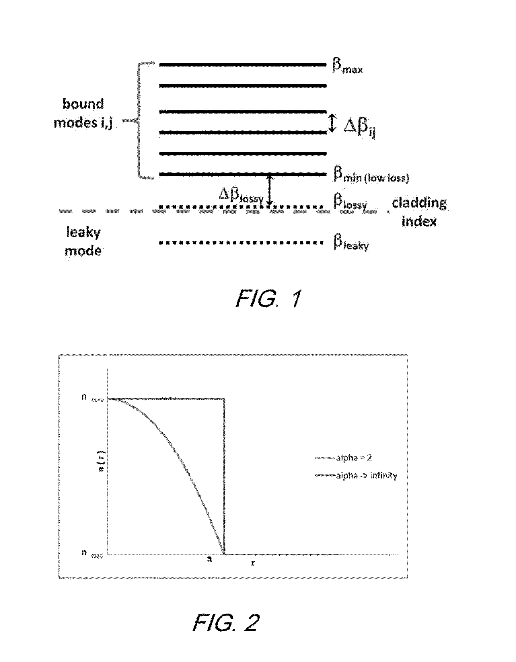
[0109]As mentioned, the refractive index profile of FIG. 2 is representative of a family of optical fiber designs that were developed specifically to support multiple modes for mode division multiplexing. Many of these designs feature an alpha core, typically having an alpha valu...
example 3
[0117]A further embodiment of the invention is represented by the refractive index profile of FIG. 16. Relevant design parameters are given in the following tables.
index regionstart deltaend deltaalphawidth (μm)10.008000.001071.97210.0020.000000.000000.0001.923−0.00410−0.004100.0003.2840.000000.000000.00047.30
1550 nm propertiesLP01LP11LP02LP21chromatic dispersion18.518.918.619.0(ps / nm·km)effective area Aeff (μm2)92.592.8186.2123.9effective index difference0.00810.00530.00250.0025
[0118]FIG. 17 gives differential group delay data for the Example 3 embodiment.
PUM
 Abstract
Description
Claims
Application Information
 - R&D
- Intellectual Property
- Life Sciences
- Materials
- Tech Scout
- Unparalleled Data Quality
- Higher Quality Content
- 60% Fewer Hallucinations
Browse by: Latest US Patents, China's latest patents, Technical Efficacy Thesaurus, Application Domain, Technology Topic, Popular Technical Reports.
© 2025 PatSnap. All rights reserved.Legal|Privacy policy|Modern Slavery Act Transparency Statement|Sitemap|About US| Contact US: help@patsnap.com


