Eureka AIR delivers breakthrough ideas for toughest innovation challenges, trusted by R&D personnel around the world.

Image processing apparatus, image processing method, and storage medium

a technology of image forming apparatus and color tone, which is applied in the direction of electrographic process apparatus, optics, instruments, etc., can solve the problems of large influence on image quality, change in density characteristics of printers, and consumption of toner, so as to prevent unnecessary calibration

Inactive Publication Date: 2015-06-18
CANON KK
View PDF4 Cites 8 Cited by
  • Summary
  • Abstract
  • Description
  • Claims
  • Application Information

AI Technical Summary

Benefits of technology

The invention helps prevent having to repeat unnecessary calibration after a calibration is completed, while still ensuring good image quality.

Problems solved by technology

It is known that the quality of an image is greatly affected by the stability of the density gradation and color.
Further, the predominant cause of the change in the density characteristics of the printer is the influence of the environment around the printer, such as temperature and humidity, the wear of the working parts caused by the processing to produce a printout, and the consumption of toner.
However, during a calibration, there is a case where the calibration is delayed on the way because the calibration requires a task of a user.
In the case where the processing is delayed after the calibration is started due to the reason such as described above, there is a possibility that the density characteristics of the printer will change on the way due to the change in the environment around the printer and the wear of a component in the idle running inside the printer in the idle state.
As described above, there is a possibility that a calibration will be delayed after the start thereof due to various kinds of causes and in the case where the calibration is delayed once, there is a possibility that the density characteristics of the printer will change on the way of the calibration.
In this case, in addition to the possibility of the previously-described delay due to the interposition of a user's task, there is a possibility that the density characteristics will change more considerably due to the consumption of toner, the wear of a component that is used, etc., resulting from the printing processing performed during the calibration.
However, in many cases, the predominant causes of the change in the density characteristics are use conditions, such as the contents of printed matter, the number of sheets on which printing processing has been performed, and the amount of consumed toner, a change in the peripheral environment, such as temperature and humidity, etc.
This will cause a user to perform the calibration again from the beginning and increase the burden of a task on the user.
Further, there can be considered a case where even though there is a change in the density characteristics actually, a calibration is not performed because the elapsed time is short, and therefore, an appropriate parameter is not obtained.
H11-179969 (1999) in which whether or not it is necessary to perform a calibration is determined based on only the elapsed time has such problems that the burden of a task on a user is increased and that a sufficient image quality is not guaranteed.

Method used


Image

  • Image processing apparatus, image processing method, and storage medium
  • Image processing apparatus, image processing method, and storage medium
  • Image processing apparatus, image processing method, and storage medium

Examples


first embodiment

Configuration of Image Forming Apparatus

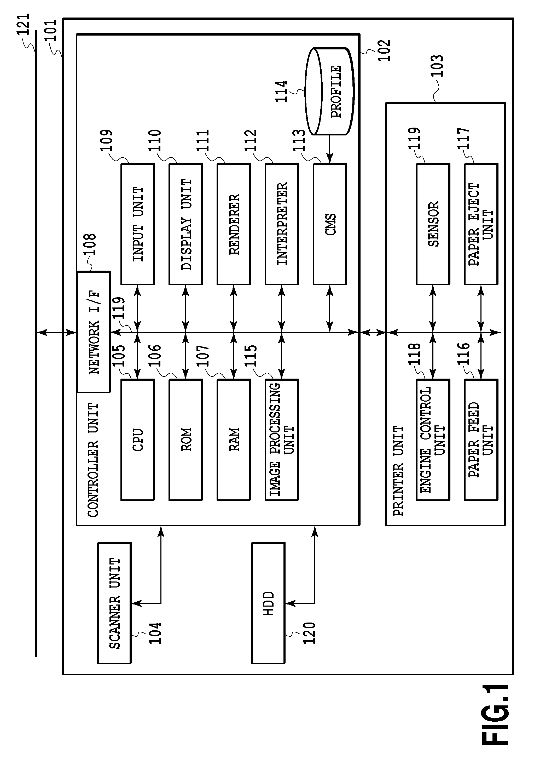
[0040]FIG. 1 is a diagram showing an internal configuration of an image forming apparatus having a calibration function according to the present embodiment.

[0041]An image forming apparatus 101 includes a controller unit 102, a printer unit 103, a scanner unit 104, and an HDD 120.

[0042]The controller unit 102 includes various kinds of modules, such as a CPU 105, and each module is connected to one another via a data bus 121. A RAM 107 loads program data stored in a ROM 106 and temporarily stores the program data. Then, the CPU 105 gives a command to each module in accordance with the program loaded on the RAM 107 and causes the image forming apparatus 101 to operate. Data etc. generated at the time of each module executing a command is also stored temporarily in the RAM 107.

[0043]A network I / F 108 is an interface module with a network 121. For example, the network I / F 108 performs data communication, such as communication with another device vi...

second embodiment

[0107]In the first embodiment, the maximum density check processing is performed for each calibration. Next, an aspect is explained as a second embodiment, in which the possibility that the density characteristics have changed is examined and the maximum density check processing is performed only in the case where the possibility is equal to or greater than a fixed value. Explanation of the portions in common to those of the first embodiment is omitted or simplified and different points are explained mainly.

[0108]In the present embodiment, by taking into consideration the possibility that the progress of the calibration will be delayed during the processing including the chart data acquisition processing and the preceding processing, the possibility that the density characteristics have changed is determined before the maximum density check processing. Specifically, whether a phenomenon that will cause the change in density has occurred during the calibration is determined based on ...

third embodiment

[0118]In the case where a calibration table is created despite the fact that the density characteristics have changed, the completed calibration table will be one that corrects the state before the density characteristics have changed. With such a calibration table, it is not possible to output the gradation of the target table (tgtLUT), and therefore, in the first and second embodiments, in the case where the amount of change in the density characteristics is equal to or more than a fixed amount, the maximum density adjustment processing is performed again from the beginning. On the other hand, in the case where the calibration is performed again from the maximum density adjustment processing, because the time required to complete the calibration increases, the time a user has to spend increases and at the same time, the amount of toner and the number of sheets that are used in the processing also increase, and therefore, the burden on the user will be great. Consequently, an aspec...


PUM


Abstract

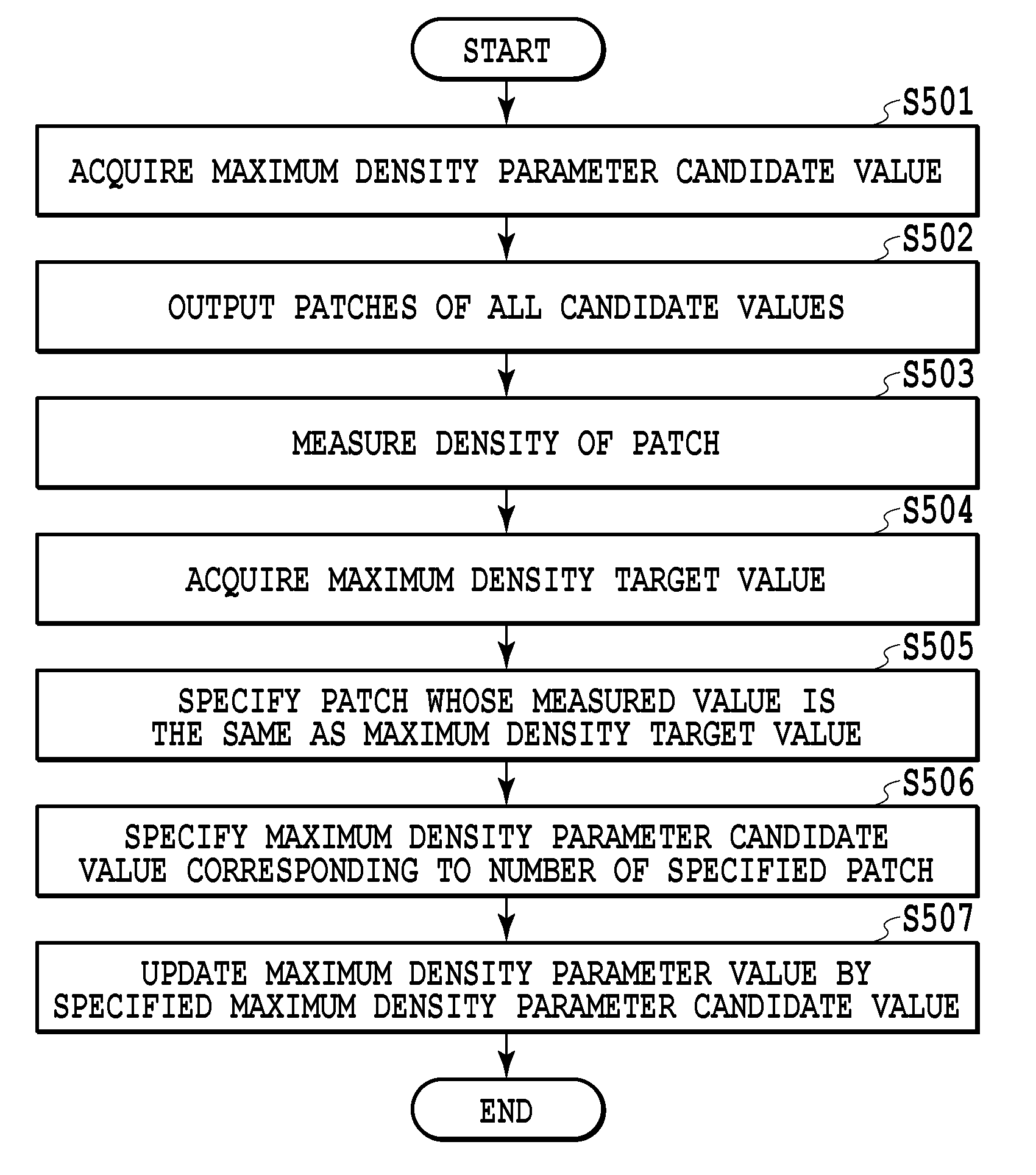
An image forming apparatus includes: a determination unit configured to determine an adjustment value for outputting a maximum density value determined in advance for a color used in forming an image by an image forming unit; an output unit configured to output a patch image by using an adjustment value determined by the determination unit; a creation unit configured to create a table for correcting a density value of an image formed by the image forming unit by using the results of measuring a patch image output by the output unit; and a control unit configured to control, before the creation unit creates a table, whether or not to cause the determination unit to determine the adjustment value again from the beginning in accordance with a difference between the density value of the patch image and the maximum density value by causing the output unit to output the patch image.

Description

BACKGROUND OF THE INVENTION[0001]1. Field of the Invention[0002]The present invention relates to a technique for correcting the color tone of an image forming apparatus, such as a printer.[0003]2. Description of the Related Art[0004]In recent years, a color image forming apparatus, such as a color printer and a color copying machine, has been increasingly requested to improve image quality of an output image. It is known that the quality of an image is greatly affected by the stability of the density gradation and color. In particular, in the color image forming apparatus adopting the electrophotographic system, even slight variations in environment will cause variations in density, and therefore, it is necessary to make is possible to keep constant at all times the gradation properties of the density.[0005]Consequently, a conventional color image forming apparatus mounts the so-called calibration function that is performed by a procedure including 1) to 3) below.[0006]1) A chart in...

Claims


Application Information

Patent Timeline
Patent Type & Authority Applications(United States)
IPC IPC(8): G03G15/00
CPCG03G15/5025G03G15/55G03G2215/0164
Inventor YASUDA, TOMOMI
Owner CANON KK
Why Eureka
Eureka Blog
Learn More