Display driving device, display driving method and display apparatus

US20150170612A1Active Publication Date: 2015-06-18FUTABA CORPORATION

Image

  • Display driving device, display driving method and display apparatus
  • Display driving device, display driving method and display apparatus
  • Display driving device, display driving method and display apparatus

Examples


Embodiment Construction

[0035]Hereinafter, an embodiment of the present invention will now be described in the following order.

[0036]1. Display Apparatus in accordance with an Embodiment

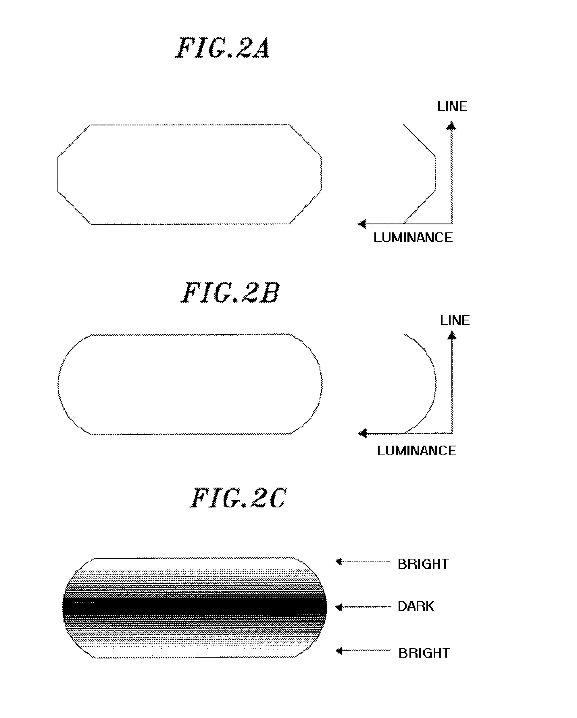
[0037]2. Description on Luminance Variation generated on Display

[0038]3. Configuration and Operation of Display Driving Device

[0039]4. Switching of Displayed Image

[0040]5. Effects of the Embodiment and Modified Examples

[0041](1. Display Apparatus in accordance with an Embodiment

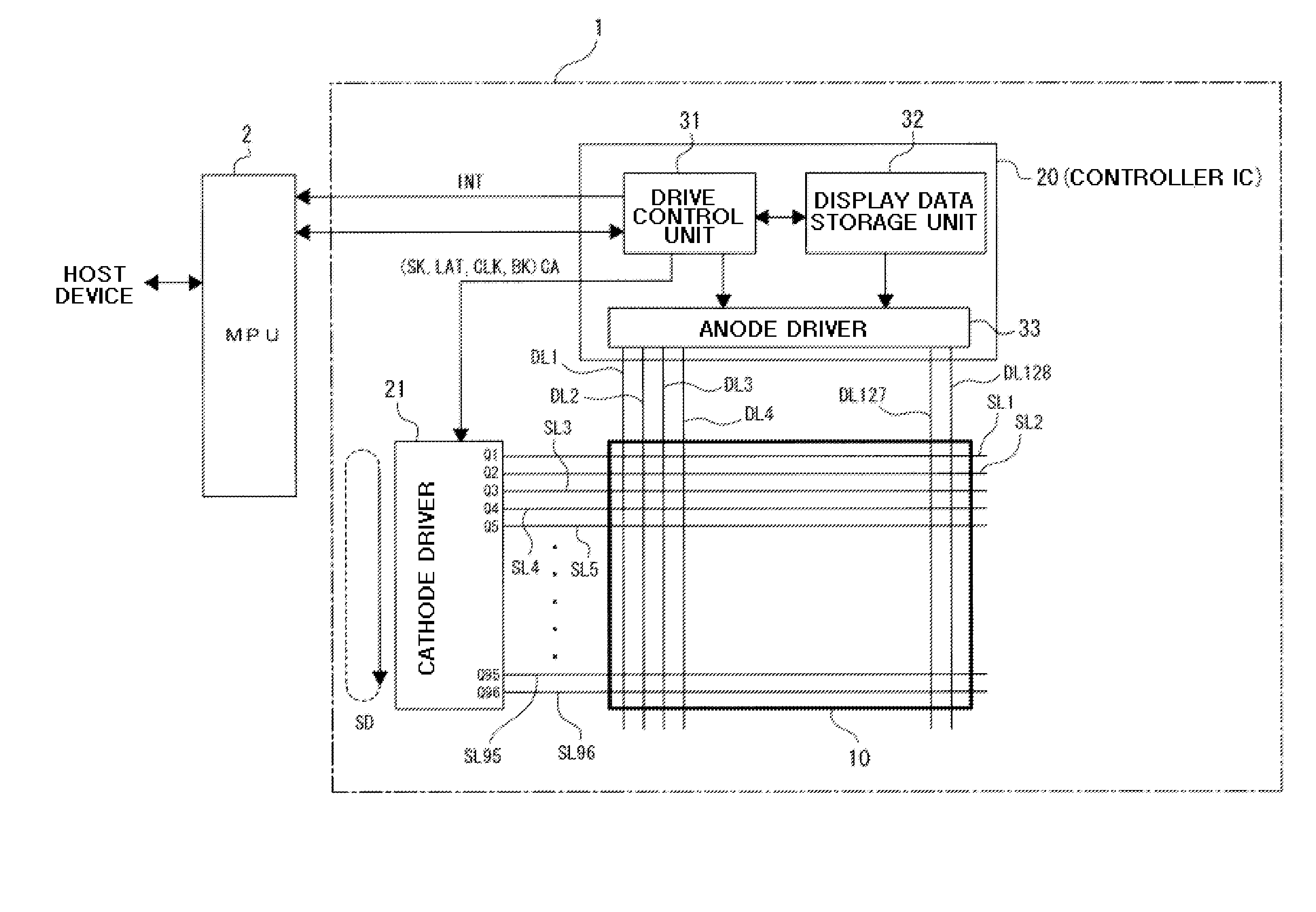
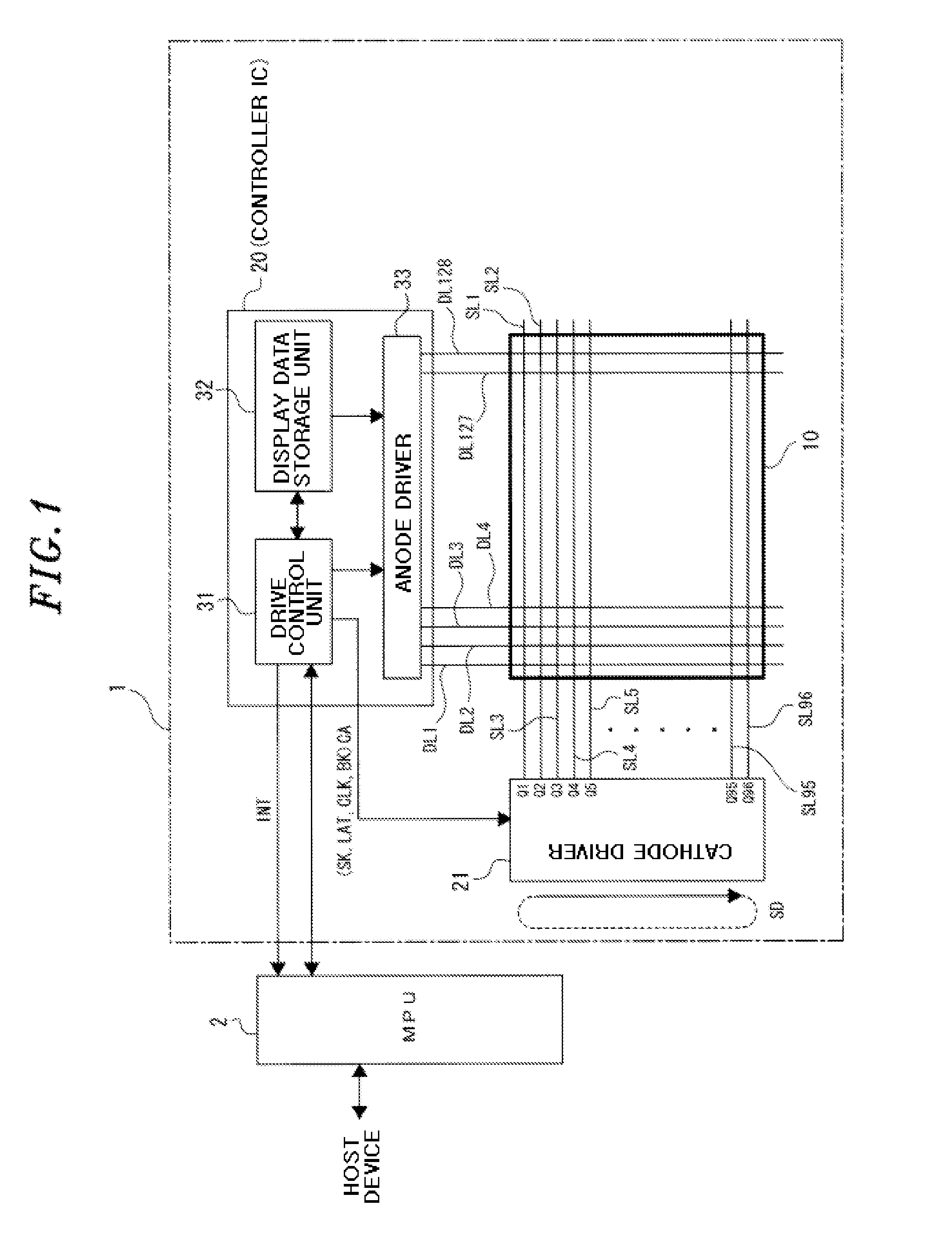
[0042]FIG. 1 shows a display apparatus 1 according to an embodiment and an MPU (Micro Processing Unit) 2 for controlling a display operation of the display apparatus 1.

[0043]The display apparatus 1 includes a display unit 10 which constitutes a display screen, a controller IC (Integrated Circuit) 20 and a cathode driver 21.

[0044]The display apparatus 1 corresponds to a display apparatus defined in the claims. The controller IC 20 corresponds to a display driving device defined in the claims.

[0045]In the example shown in FIG. 1, the cathode driver 21 ...


PUM


Abstract

A display driving device performs display drive based on display data with respect to a display unit including pixels arranged at respective intersections of data lines and scanning lines. The device includes: a current setting unit configured to store current gradation values which are set for the respective scanning lines that constitute a frame of the display data; a current gradation control unit configured to, at each of scan timings for the respective scanning lines within one frame, generate a constant current corresponding to a current gradation value for a corresponding scanning line among the current gradation values stored in the current setting unit; and a data line driving unit configured to supply the constant current generated by the current gradation control unit to the respective data lines for time periods corresponding to pixel gradation values defined by the display data.

Description

CROSS-REFERENCE TO RELATED APPLICATION[0001]This application claims priority to Japanese Patent Application No. 2013-259168 filed on Dec. 16, 2013, the entire contents of which are incorporated herein by reference.FIELD OF THE INVENTION[0002]The present invention relates to a display driving device, a display driving method and a display apparatus. More particularly, the present invention relates to a technology for driving a display unit in which a plurality of data lines and a plurality of scanning lines are provided and in which pixels are arranged at intersections of the data lines and the scanning lines.BACKGROUND OF THE INVENTION[0003]As display panels for displaying an image, there are known a display apparatus that makes use of an OLED (Organic Light Emitting Diode) and a display apparatus that makes use of an LCD (Liquid Crystal Display). Many display apparatuses include a display unit in which data lines each connected to a plurality of pixels arranged in a column directio...

Claims


Application Information

Patent Timeline
18 Jun 2015
Publication
US20150170612A1
IPC
G09G5/18; G09G3/32; G09G3/36
CPC
G09G5/18; G09G3/3283; G09G3/3685; G09G3/3216; G09G3/3275; G09G2300/0426; G09G2310/0243; G09G2310/0272
Inventors
MUGURUMA, TAKASHI; SUGIMOTO, TERUKAZU