Check patentability & draft patents in minutes with Patsnap Eureka AI!

Electronic Device

Active Publication Date: 2015-06-18
WISTRON CORP
View PDF7 Cites 0 Cited by
  • Summary
  • Abstract
  • Description
  • Claims
  • Application Information

AI Technical Summary

Benefits of technology

The invention provides a structure for a communication device that includes a supporting frame with a notch for disposing an antenna. The design allows for the antenna to be placed on the right or left side of the display, ensuring sufficient space for other electronic elements such as an image-capturing unit. The notch on the supporting frame serves as a ground element, eliminating the need for a separate copper foil ground layer. This simplifies assembly and reduces costs. Additionally, the supporting frame can be electrically connected to the pivot structure via a connection element to further increase ground area and achieve improved ground effect. Overall, this structure improves antenna performance and reduces signal transmission noise while maintaining sufficient space for other components.

Problems solved by technology

However, with the increased multifunctional requirements of the notebook (or tablet computer), more and more electronic elements should be disposed at the top of the screen, and the mounting space at the top side of the screen inside the notebook is insufficient.
When the antenna is adjacent to the image-capturing unit, noise can occur, and transmission of the antenna is deteriorated.
The conventional design has a complicated assembly process and an increased cost.

Method used


Image

  • Electronic Device
  • Electronic Device
  • Electronic Device

Examples


Embodiment Construction

[0017]The following description is of the best-contemplated mode of carrying out the invention. This description is made for the purpose of illustrating the general principles of the invention and should not be taken in a limiting sense. The scope of the invention is best determined by reference to the appended claims.

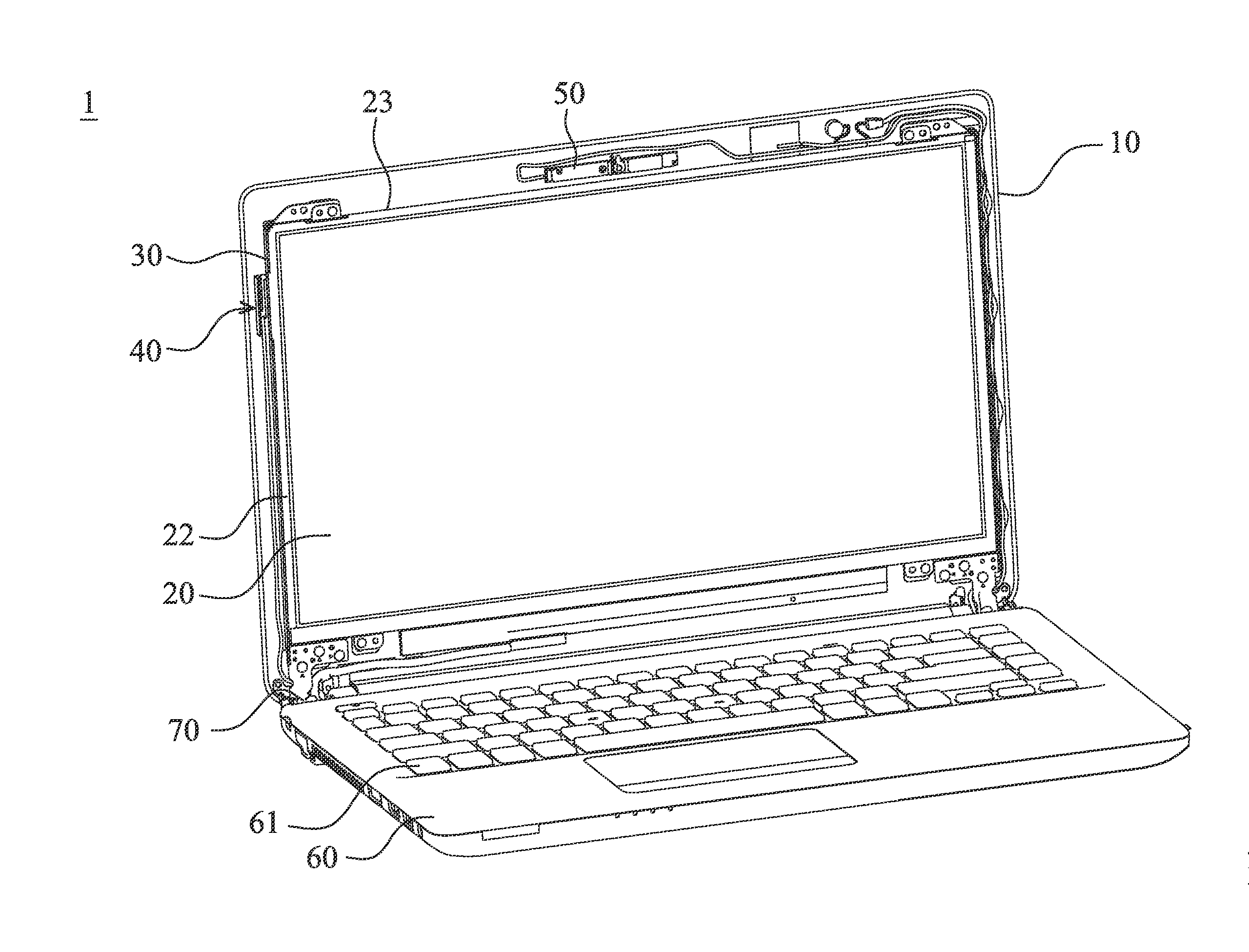
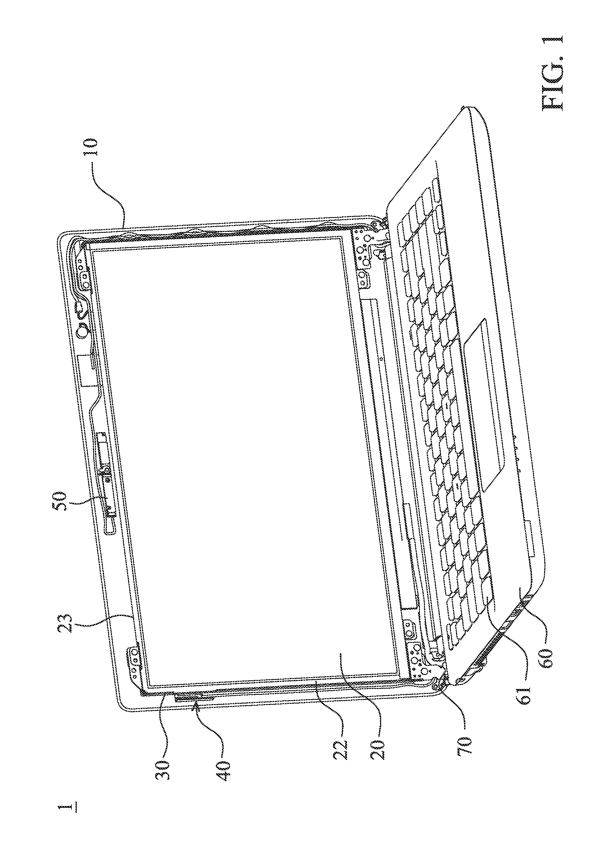
[0018]FIG. 1 shows an electronic device 1 of an embodiment of the invention, comprising a housing 10, a display 20, a supporting frame 30 and an antenna 40. The display 20 is disposed in the housing 10. The supporting frame 30 contacts and supports the display 20. In this embodiment, the supporting frame 30 contacts the lateral sides (right, left, top and bottom sides) and the back side of the display 20.

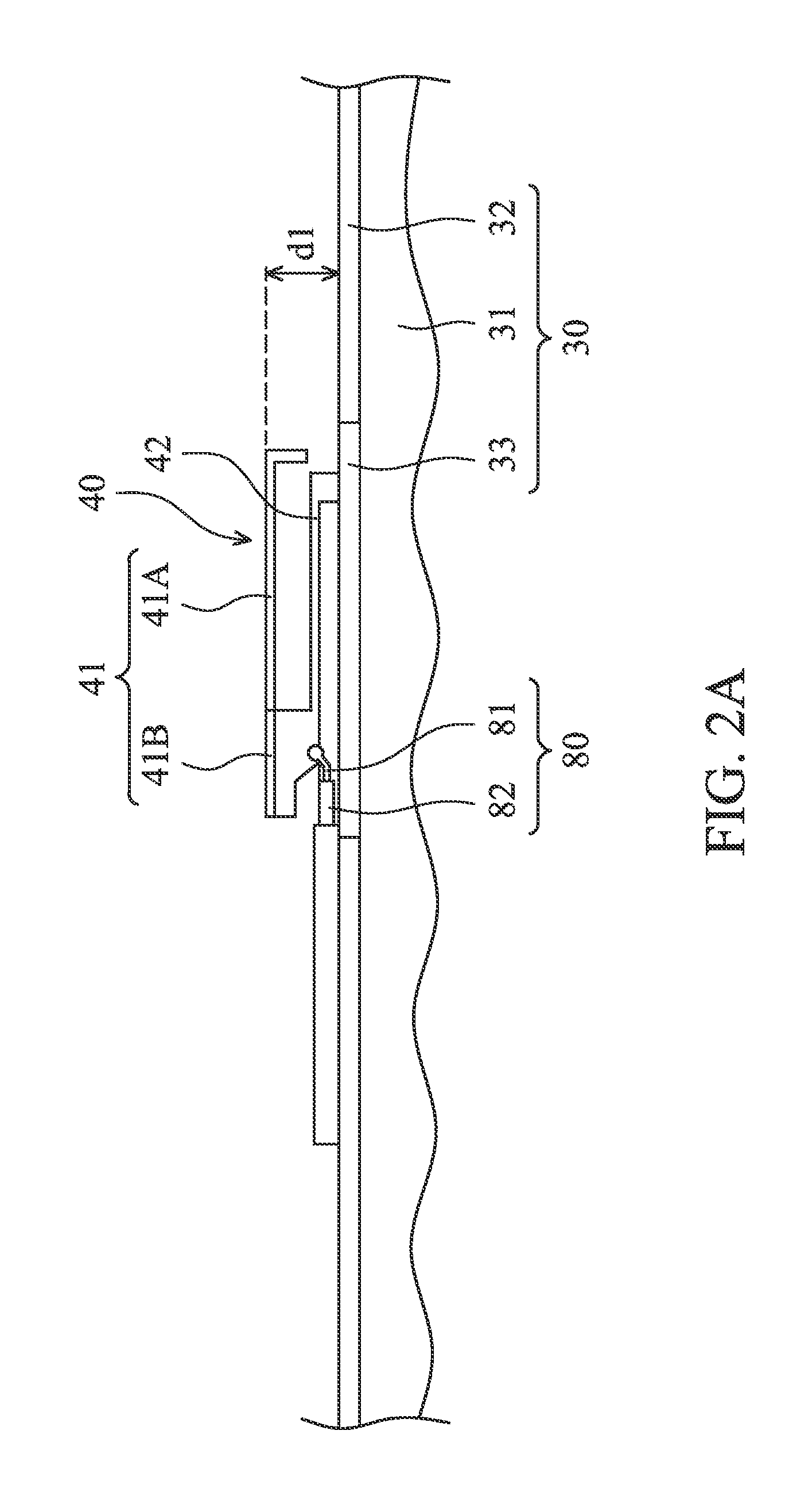
[0019]FIG. 2A shows the detailed structure of the antenna 40. The antenna 40 comprises a radiator 41 and a connection section 42. The connection section 42 is connected to the radiator 41, wherein the connection section 42 is coupled (connected) to the supporting frame...


PUM


Abstract

An electronic device is provided. The electronic device includes a housing, a display, a supporting frame and an antenna. The display is disposed in the housing. The supporting frame supports the display. The antenna includes a radiator and a connection section. The connection section is connected to the radiator, wherein the connection section is coupled to the supporting frame.

Description

CROSS REFERENCE TO RELATED APPLICATIONS[0001]This Application claims priority of Taiwan Patent Application No. 102146837, filed on Dec. 18, 2013, the entirety of which is incorporated by reference herein.BACKGROUND OF THE INVENTION[0002]1. Field of the Invention[0003]The present invention relates to an electronic device, and in particular to an electronic device including an antenna.[0004]2. Description of the Related Art[0005]In a conventional notebook or tablet computer, an antenna is disposed at a top side of a screen, and is arranged side by side with an image-capturing unit. However, with the increased multifunctional requirements of the notebook (or tablet computer), more and more electronic elements should be disposed at the top of the screen, and the mounting space at the top side of the screen inside the notebook is insufficient. When the antenna is adjacent to the image-capturing unit, noise can occur, and transmission of the antenna is deteriorated.[0006]Additionally, in ...

Claims


Application Information

Patent Timeline
IPC IPC(8): H01Q1/22H01Q1/24
CPCH01Q1/243H01Q1/2266H01Q1/48H01Q9/42
Inventor LEI, CHUN-HSIANGSUN, YUAN-CHENGCHEN, CHIEN-JUCHU, PO-HSIEN
Owner WISTRON CORP
Features
  • R&D
  • Intellectual Property
  • Life Sciences
  • Materials
  • Tech Scout
  • Unparalleled Data Quality
  • Higher Quality Content
  • 60% Fewer Hallucinations
Learn More