
Wireless power transmission network and wireless power transmission method

a technology of wireless power transmission and wireless transmission, which is applied in the direction of transformers, inductances, transportation and packaging, etc., can solve the problem of drastic degradation of the transmission efficiency of inductive coupling, and achieve the effect of effective power transfer to a plurality

Active Publication Date: 2015-06-18
INTELLECTUAL DISCOVERY CO LTD
View PDF2 Cites 250 Cited by
  • Summary
  • Abstract
  • Description
  • Claims
  • Application Information

AI Technical Summary

Benefits of technology

The present invention provides a wireless power transmission system that can efficiently transfer power to multiple electronic devices. The base station communicates with the electronic devices to determine which ones are in a charging zone and allocate time slots for them only. This ensures that power is effectively transferred to the devices. The system also prioritizes electronic devices with higher priority levels, such that urgent charging needs can be met first, improving user convenience. Overall, the system ensures efficient and effective wireless power transfer to multiple electronic devices.

Problems solved by technology

Inductive coupling, however, is so vulnerable to a distance between two coils or relative positions thereof that transmission efficiency of inductive coupling is drastically degraded if two coils become away a little further or deviate.

Method used


Image

  • Wireless power transmission network and wireless power transmission method
  • Wireless power transmission network and wireless power transmission method
  • Wireless power transmission network and wireless power transmission method

Examples


Embodiment Construction

[0037]Embodiments described in this disclosure are provided to clarify the technical concept of the present invention for a person skilled in the art to which the present invention pertains, and thus, the present invention is not limited to the embodiments described in this disclosure and the scope of the present invention should be interpreted to include any modification without departing from the scope of the present invention.

[0038]The terms used in this disclosure and accompanying drawings help to describe the present invention easily, and the shapes illustrated in drawings are exaggerated for clarity, so the present invention is not limited by the terms used in this disclosure and the accompanying drawings.

[0039]If a detailed explanation for a related known function or construction is considered to unnecessarily divert the gist of the present invention, such explanation has been omitted but would be understood by those skilled in the art.

[0040]According to an aspect of the pres...


PUM


Abstract

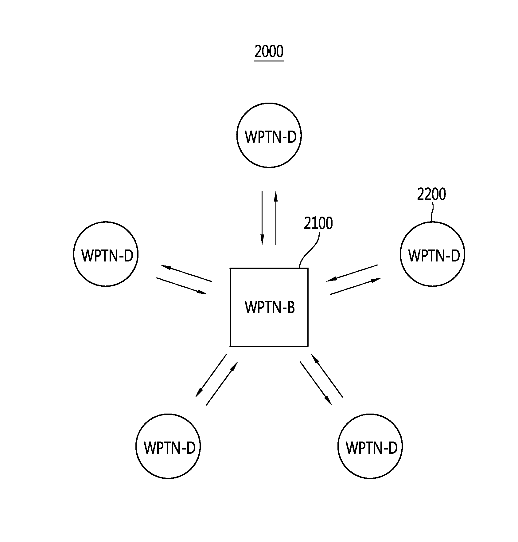
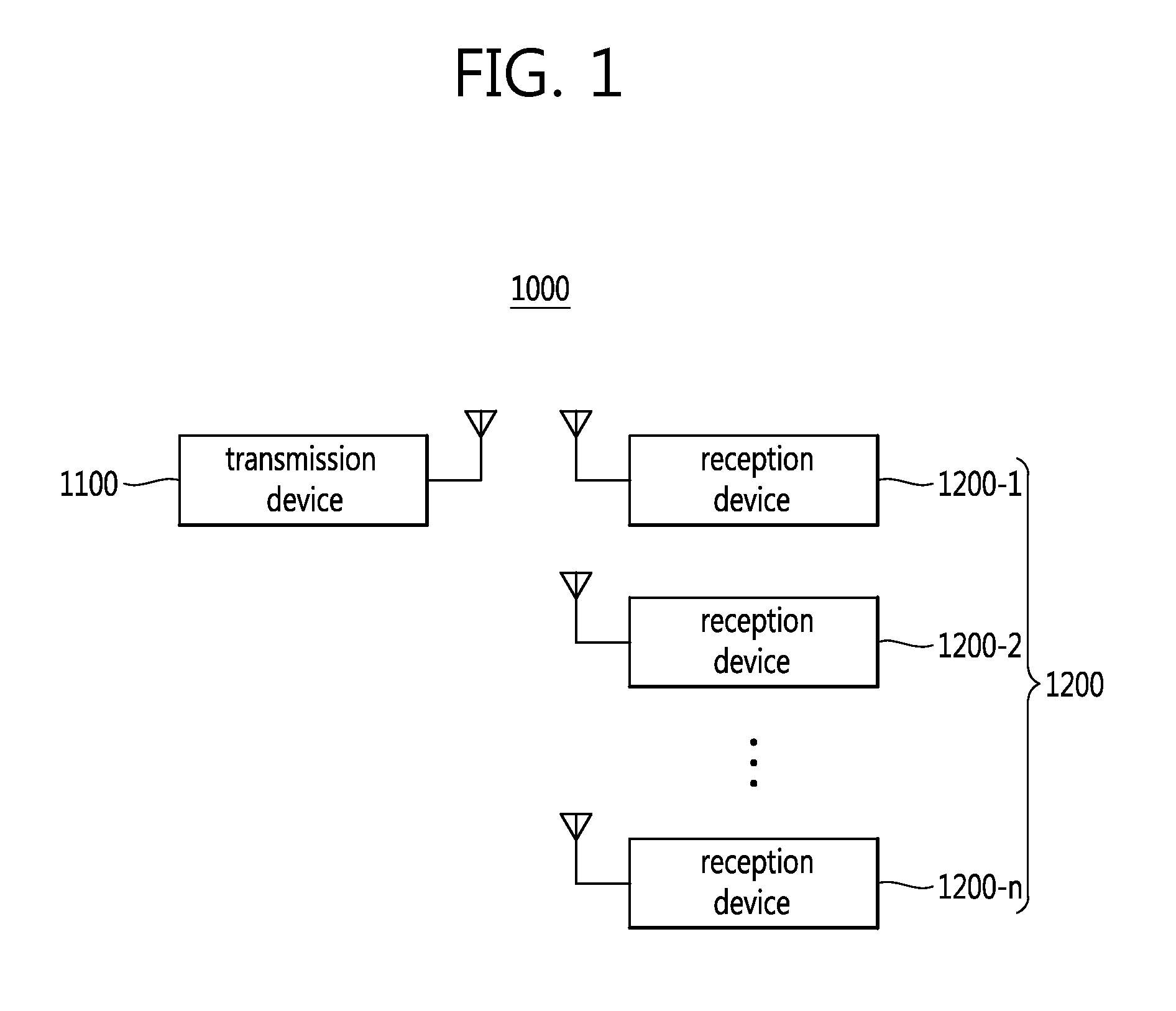
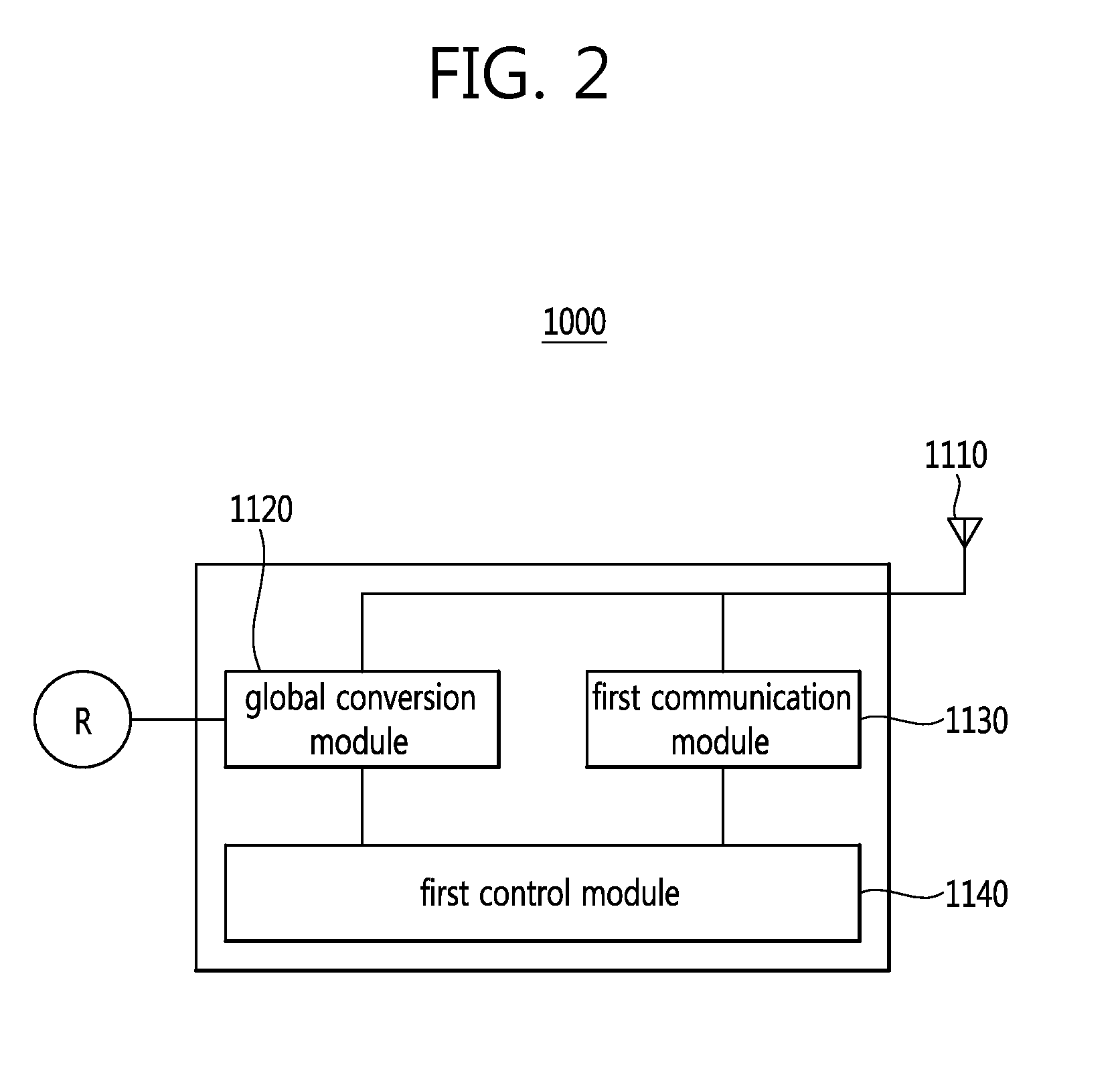
The present invention relates to a wireless power transmission network and to a wireless power transmission method. In the wireless power transmission method according to one aspect of the present invention, a base station, which wirelessly transmits power using a magnetic field, performs in-band communication through the magnetic field used for wireless power transmission in order to determine whether an electronic device receiving power is in a charging area or in a communication area, and transmits wireless power accordingly.

Description

BACKGROUND OF THE INVENTION[0001]1. Field of the Invention[0002]The present invention relates to a wireless power transfer network and a wireless power transmission method and, more particularly, to a wireless power transfer network for wirelessly transferring power by using a magnetic field and performing in-band communication through a magnetic field used for wireless power transmission and a wireless power transmission method using the same.[0003]2. Related Art[0004]A wireless power transmission technique is a technique of transferring power between a power source and an electronic device without a line or a contact, which is anticipated to be utilized in various fields including home appliances, medical treatment, leisure, robots, automobiles, and the like.[0005]The wireless power transmission technique is classified as inductive coupling and resonant magnetic coupling.[0006]Inductive coupling is a scheme of transferring energy by inducing a current through a magnetic field from...

Claims


Application Information

Patent Timeline
IPC IPC(8): H04B5/00H02J7/02H02J5/00H01F38/14
CPCH04B5/0037H01F38/14H01F2038/143H02J5/005H02J7/025H02J50/12H02J7/00712H02J50/80H02J50/40H02J50/10
Inventor WON, YUNJAELIM, SEUNGOK
Owner INTELLECTUAL DISCOVERY CO LTD
Learn More