Imaging device and imaging method

a technology of imaging device and image, applied in the direction of color signal processing circuit, color television details, television system, etc., can solve the problems of ineffective flicker detection and correction, adverse effect of live view display or movie shooting,

Active Publication Date: 2015-06-18
OM DIGITAL SOLUTIONS CORP
View PDF6 Cites 25 Cited by
  • Summary
  • Abstract
  • Description
  • Claims
  • Application Information

AI Technical Summary

Problems solved by technology

At the time of shooting a movie indoors or performing Live view display, a light source such as a fluorescent lamp may vary in brightness periodically in synchronization with frequency of the mains power supply, and have an adverse effect on Live view display or movie shooting.
This method can not carry out flicker detection and correction effectively in a situation where live view display or movie recording is carried out at a frame frequency that is the same as or slower than the flicker period of the light source.

Method used


Image

  • Imaging device and imaging method
  • Imaging device and imaging method
  • Imaging device and imaging method

Examples


Embodiment Construction

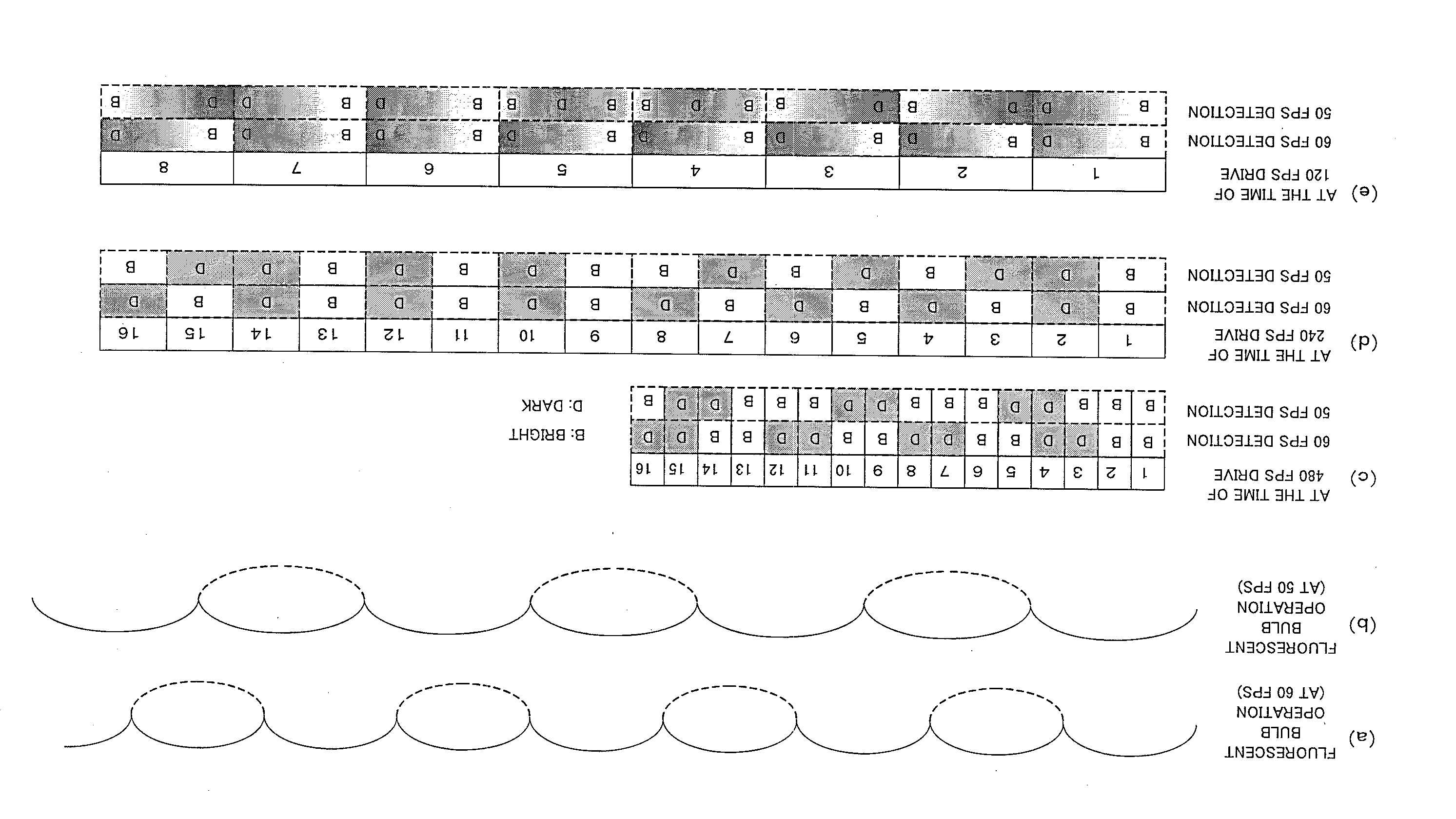
[0020]Preferred embodiments using a camera as one example to which the present invention has been applied will be described in the following in accordance with the drawings. With one aspect of the present invention, there is provided an imaging device and an imaging method capable of canceling flicker in high-speed camera mode, even in a portable device such as a digital camera.

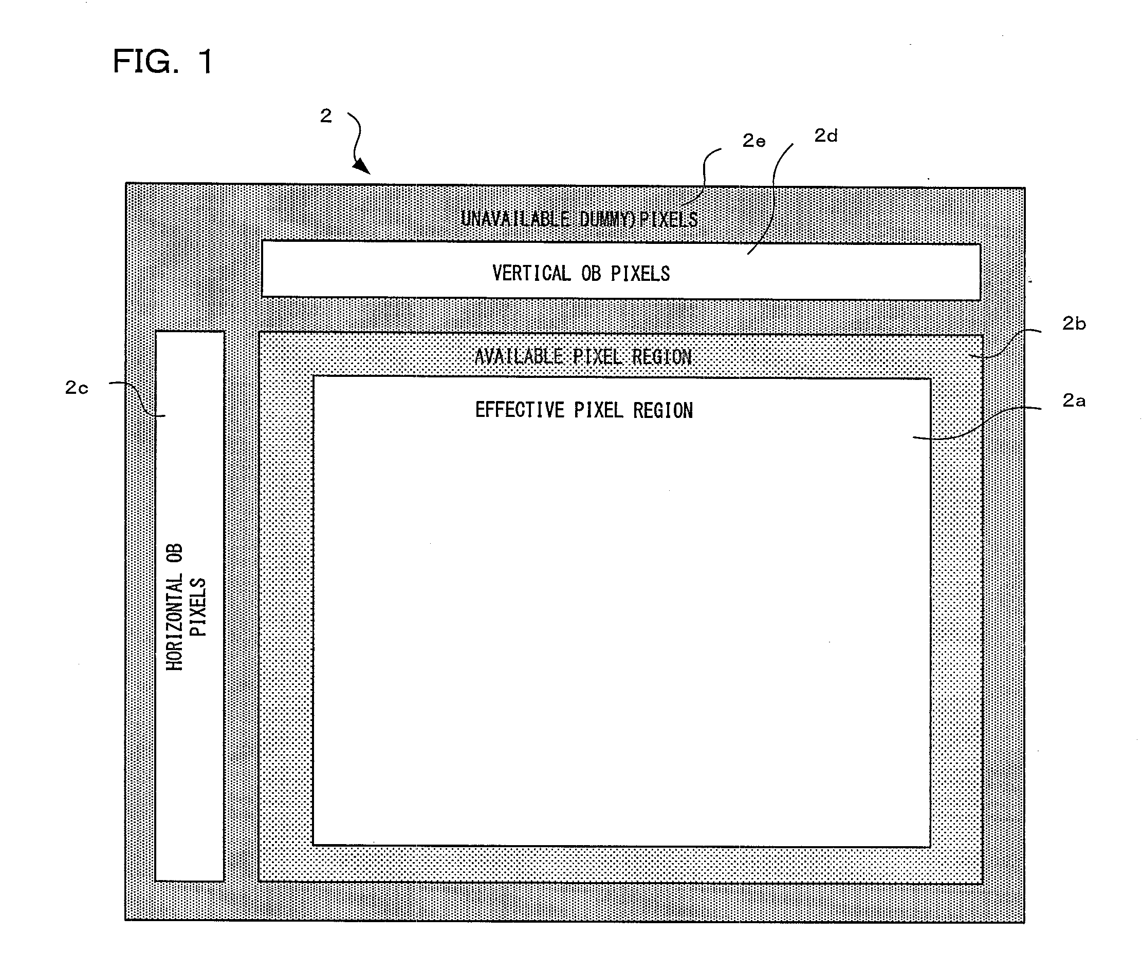
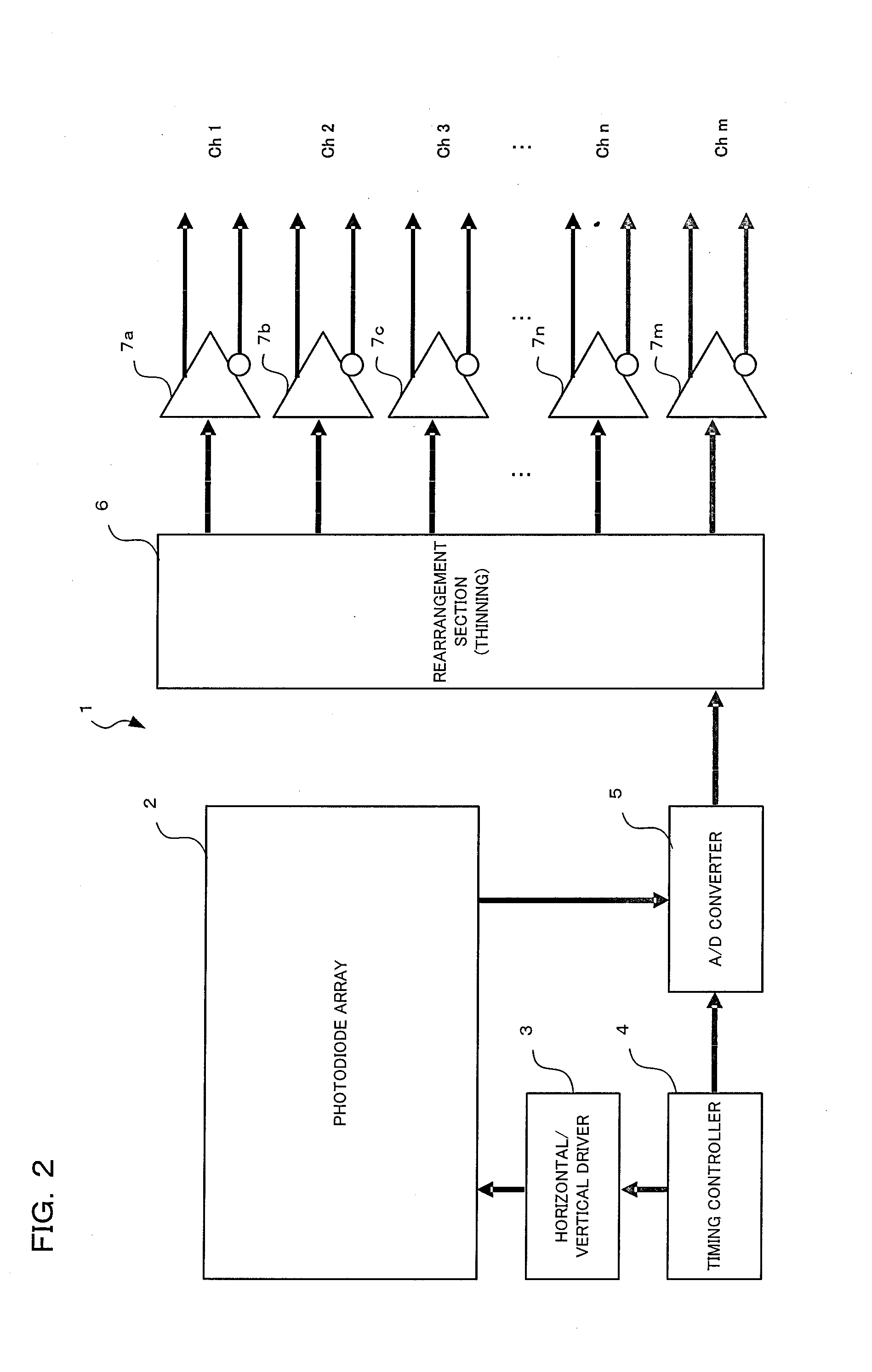
[0021]A camera of a preferred one embodiment of the present invention is a digital camera having an imaging section such as an image sensor. This imaging section converts a subject image that has been formed by a photographing lens into image data. Output of an image sensor within the imaging section is made up of a two system, namely system 1 for outputting data of a first pixel group, and system 2 for outputting data of a second pixel group, and it is possible to independently set respective frame rates for read out (in other words, it is possible to respectively independently set an electronic shutter spee...


PUM


Abstract

An imaging device of the present invention comprises an image sensor having a plurality of pixels made up of a first pixel group and a second pixel group, a flicker detection section for detecting bright states and dark states of all taken images based on a periodic flicker action of a light source contained in a subject from image output from the second pixel group, and a flicker correction calculation section 4 for, when light of brightness having bright states and dark states due to periodic flicker is incident, correcting brightness output gain corresponding to all pixels of the plurality of pixels corresponding to the first pixel group so that brightness output of taking images from the first pixel group becomes a standard brightness output.

Description

[0001]Benefit is claimed, under 35 U.S.C. §119, to the filing date of prior Japanese Patent Application No. 2013-259054 filed on Dec. 16, 2013. This application is expressly incorporated herein by reference. The scope of the present invention is not limited to any requirements of the specific embodiments described in the application.BACKGROUND OF THE INVENTION[0002]1. Field of the Invention[0003]The present invention relates to an imaging device and imaging method that alleviate light source flicker, even in situations where a subject is illuminated by exterior lighting for which an amount of flicker varies periodically.[0004]2. Description of the Related Art[0005]At the time of shooting a movie indoors or performing Live view display, a light source such as a fluorescent lamp may vary in brightness periodically in synchronization with frequency of the mains power supply, and have an adverse effect on Live view display or movie shooting. This phenomenon is called light source flicke...

Claims


Application Information

Patent Timeline
Patent Type & Authority Applications(United States)
IPC IPC(8): H04N5/235H04N5/378H04N5/347H04N5/243
CPCH04N5/2357H04N5/243H04N2209/042H04N5/347H04N5/378H04N23/667H04N23/745H04N23/76H04N25/445H04N25/75
Inventor AOTA, KOJI
Owner OM DIGITAL SOLUTIONS CORP
Why Eureka
Try Eureka