Unlock instant, AI-driven research and patent intelligence for your innovation.

Handover optimization system, handover optimization control device, and handover parameter adjustment device

Inactive Publication Date: 2015-06-18
NEC CORP
View PDF3 Cites 5 Cited by
  • Summary
  • Abstract
  • Description
  • Claims
  • Application Information

AI Technical Summary

Benefits of technology

This patent describes a system and method for optimizing handovers between different cells in a communication network. The system takes into account the different sensitivities of each cell to changes in the handover parameters, such as failure rates and ping-pong handover rates. This allows for efficient handovers across multiple cells, improving overall network performance.

Problems solved by technology

However, when the initiation of the handover is too late or too early, a connection failure involving abnormal disconnection of a radio link (hereinafter referred to as RLF (Radio Link Failure)) occurs.

Method used


Image

  • Handover optimization system, handover optimization control device, and handover parameter adjustment device
  • Handover optimization system, handover optimization control device, and handover parameter adjustment device
  • Handover optimization system, handover optimization control device, and handover parameter adjustment device

Examples


first embodiment

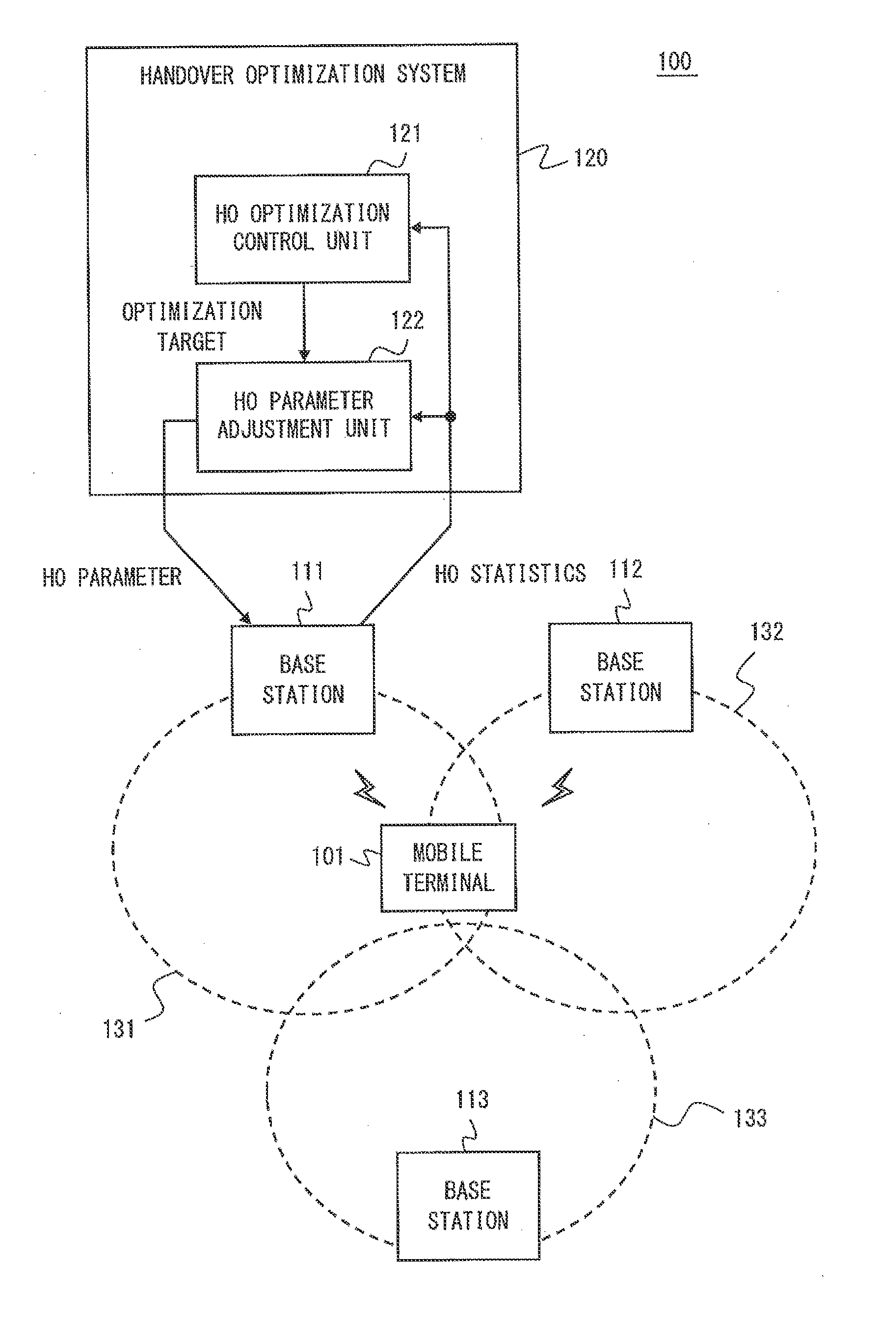
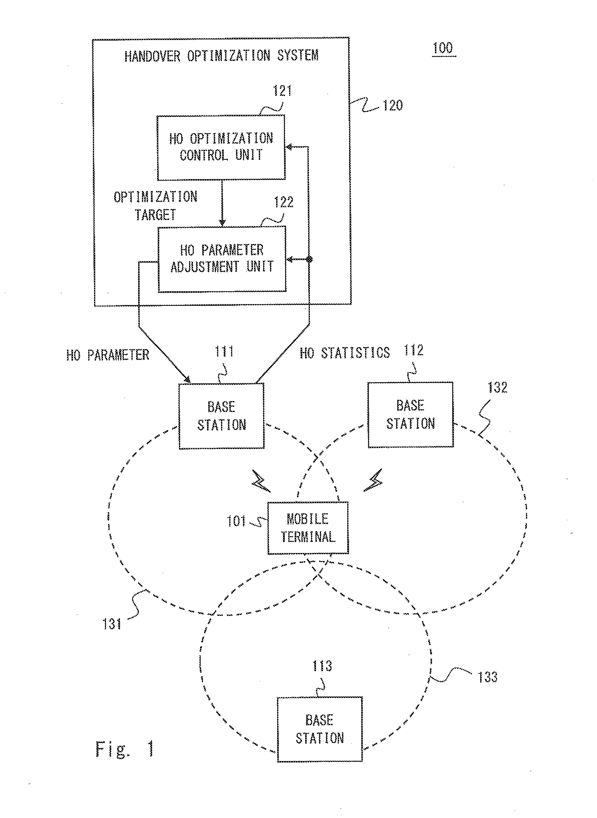
[0044]FIG. 1 is a block diagram showing a configuration example of a radio communication system 100 according to some embodiments including the present embodiment. The radio communication system 100 includes a plurality of base stations 111 to 113. The base stations 111 to 113 manage cells 131 to 133, respectively, and communicate with one or more mobile terminals (e.g., a mobile terminal 101). The mobile terminal 101 can be connected to any one of the base stations 111 to 113. It is to be noted that the configuration example of FIG. 1 may be appropriately changed since it is merely one example for explanation. For example, the radio communication system 100 may include four or more base stations. In addition, neighborhood relations of the cells 131 to 133 shown in FIG. 1 are also merely one example. For example, the radio communication system 100 may have a hierarchical cell structure in which a certain cell (e.g., the cell 132) is arranged within another cell (e.g., the cell 133)....

second embodiment

[0059]The present embodiment describes a specific example of changing a handover optimization target according to a measurement value of an HPI. A configuration example of the radio communication system 100 according to the present embodiment is the same as FIG. 1. FIG. 7 is a graph for visualizing and illustrating an optimization target according to measurement values of a handover failure rate and a ping-gong handover rate. In an example of FIG. 7, a plane defined by a handover failure rate (0 to 100%) and a ping-pong handover rate (0 to 100%) is divided into two regions (the regions 1 and 2). The threshold value P1 shown in FIG. 7 is applied to the ping-pong handover rate.

[0060]FIG. 8 is a flow chart showing an example of a procedure for determining an optimization target by the HO optimization control unit 121 according to the present embodiment. In step S31, the HO optimization control unit 121 acquires a measurement value of a ping-pong handover rate regarding the cell 131. Th...

third embodiment

[0070]The present embodiment describes another specific example of changing the handover optimization target according to the measurement value of the HPI. A configuration example of the radio communication system 100 according to the present embodiment is to the same as FIG. 1. FIG. 10 is a graph for visualizing and illustrating an optimization target according to measurement values of a handover failure rate and a ping-pong handover rate. In an example of FIG. 10, a plane defined by a handover failure rate (0 to 100%) and a ping-pong handover rate (0 to 100%) is divided into three regions. The threshold value P1 shown in FIG. 10 is applied to the ping-pong handover rate, and the threshold value F1 is applied to the handover failure rate. Namely, in FIG. 10, the region 2 of FIG. 7 is further divided into two regions (the regions 2 and 3 of FIG. 10)

[0071]FIG. 11 is a flow chart showing an example of a procedure for determining an optimization target by the HO optimization control un...


PUM


Abstract

An adjustment unit (122) operates so as to adjust a handover parameter applied to a first cell (131), in accordance with an optimization target defined using at least one of a plurality of performance indicators regarding outgoing handover of a mobile terminal (101) from the first cell (131). A control unit (121) changes the optimization target for adjusting the handover parameter, according to a measurement value of the at least one of the plurality of performance indicators relating to the first cell (131). As a result, handover optimization for a plurality of cells, having different handover-performance-indicator sensitivity with respect to change of an HO parameter, can be performed effectively and generically.

Description

TECHNICAL FIELD[0001]The present application relates to optimization of handover parameters.BACKGROUND ART[0002]In a radio communication system, in moving from a serving cell (source cell) to another cell, a mobile terminal performs switching processing of the serving cell called handover, and continues communication. In order to achieve handover of a mobile terminal, a base station that manages the source cell instructs the mobile terminal to transmit a measurement report when a predetermined event occurs. The predetermined event is, for example, deterioration of radio quality of the source cell. The measurement report generated by the mobile terminal includes measurement results of radio quality of the source cell and its neighboring cells. In response to receiving the measurement report from the mobile terminal, the base station of the source cell determines a cell (target cell) to which a radio link connection switches based on the measurement report, and initiates a handover pr...

Claims


Application Information

Patent Timeline
IPC IPC(8): H04W36/00
CPCH04W36/0055H04W24/02H04W36/00837H04W36/00835
Inventor WATANABE, YOSHINORI
Owner NEC CORP
Features
  • R&D
  • Intellectual Property
  • Life Sciences
  • Materials
  • Tech Scout
  • Unparalleled Data Quality
  • Higher Quality Content
  • 60% Fewer Hallucinations
Learn More