Transcatheter Mitral Valve Replacement Apparatus

a technology of transcatheter and mitral valve, which is applied in the field of medical devices, can solve the problems of abnormal tension and angulation of the mitral valve leaflet, the less invasive surgical procedure is not as well developed for replacing abnormally functioning mitral valves, and the flow of regurgitants that require repair or replacement of valves, etc., to achieve the effect of reducing the delivery profile of the replacement valve, reducing thrombosis, and improving blood flow

Inactive Publication Date: 2015-06-25
DRASLER WILLIAM JOSEPH +3
View PDF5 Cites 102 Cited by
  • Summary
  • Abstract
  • Description
  • Claims
  • Application Information

AI Technical Summary

Benefits of technology

The present invention describes an adaptor that enables replacing a damaged heart valve with a small prosthetic one through catheters placed into the body. This reduces the size of the surgery needed and makes it possible to use existing technology on larger patients. Additionally, this design improves how blood flows around the new valve, reducing clotting and other complications.

Problems solved by technology

This patent discusses the problem of replacing damaged mitrial valves through traditional open heart surgeries being highly invasive and potentially risky for patients. A new method is needed for less invasive mitral valve replacement that reduces the likelihood of blocking blood flow and allows for better hemodynamics preservation.

Method used


Image

  • Transcatheter Mitral Valve Replacement Apparatus
  • Transcatheter Mitral Valve Replacement Apparatus
  • Transcatheter Mitral Valve Replacement Apparatus

Examples


Embodiment Construction

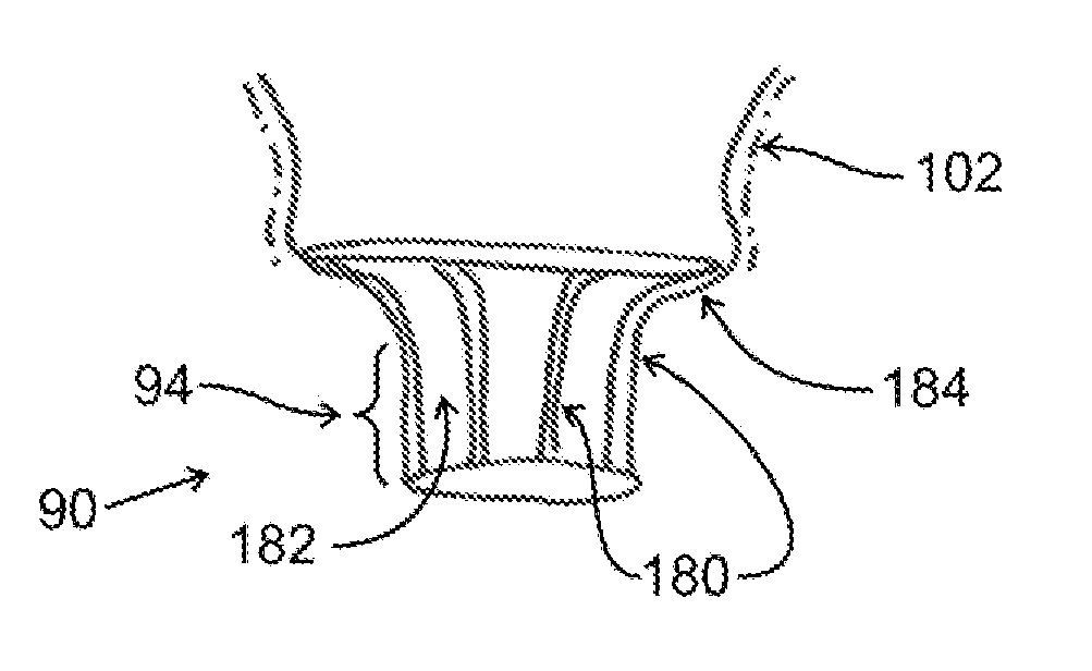
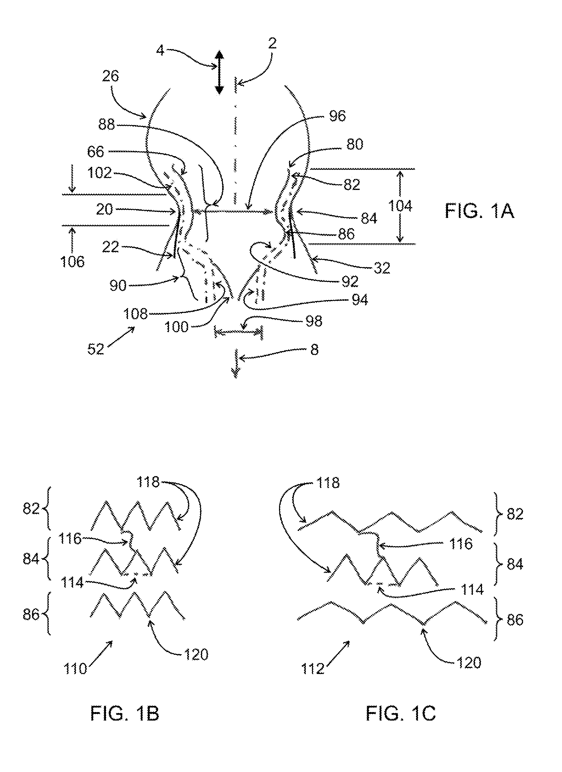
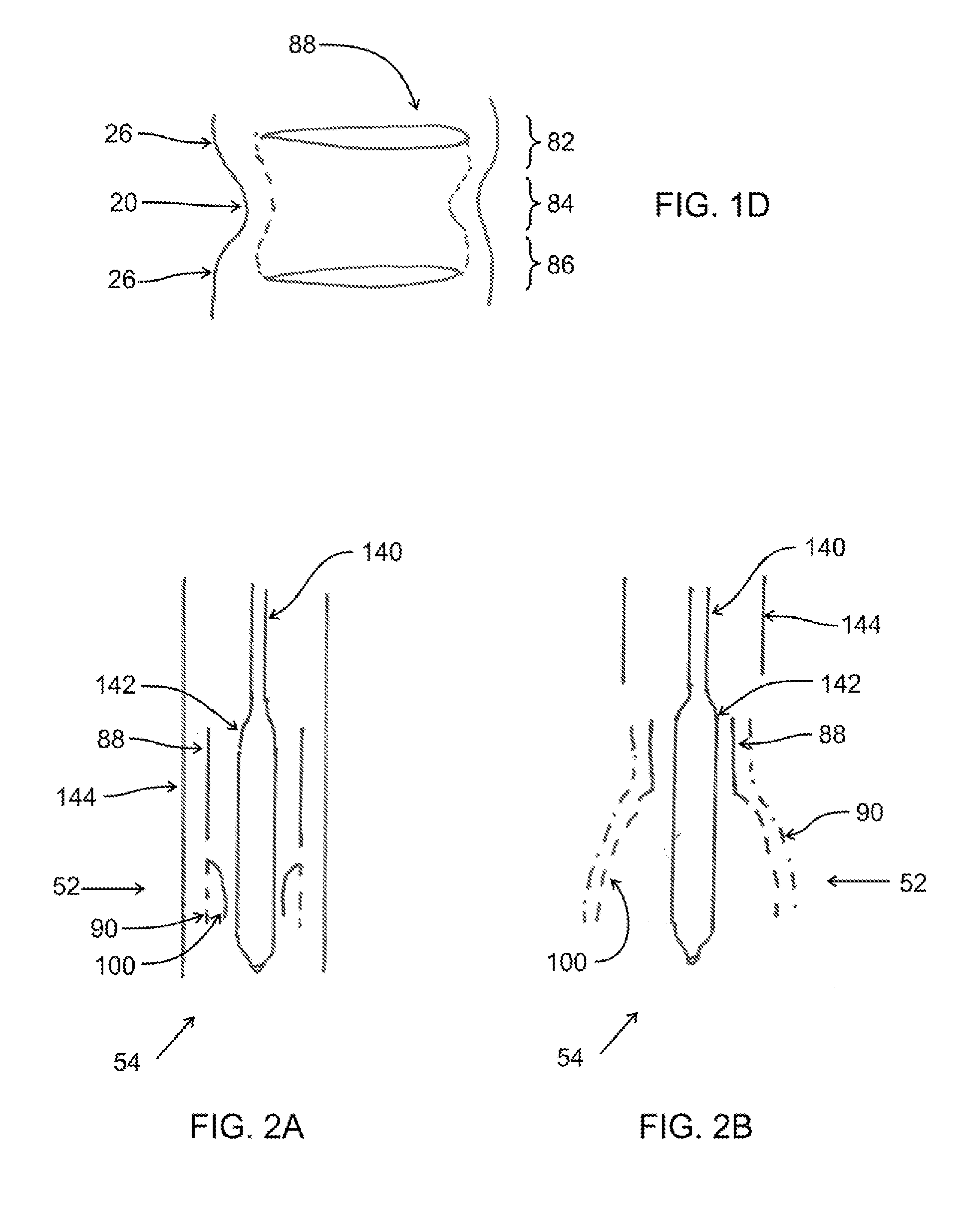
[0117]One embodiment of the valve of the present invention is shown in FIGS. 1A-1D. Replacement valve 52 has a mitral annular holding structure or stent 66 comprising stabilizing portion 88. Replacement valve 52 also comprises tract element 90. Stabilizing portion 88 of stent 66 for this embodiment is formed from a BE material such as stainless steel, cobalt alloy, or other materials, including polymeric materials used for forming stents; the BE material can also be NiTi or other elastic metals used in medical stents that is machined to form a focused region at the expansion sites that will deform plastically. Stabilizing portion 88 has a waist 84 with a waist diameter 96 that is somewhat smaller than the mitral annulus 20 to which it is positioned adjacently. A somewhat enlarged region or upper bulb 82 is joined to waist 84 and is of a larger diameter by approximately 2-10 mm than waist 84; the upper bulb 82 preferably has a free end 80 which is curved toward the centerline or axis...


PUM


Abstract

Transcatheter mitral valve replacement is provided which includes a stabilizing stent portion for placement at a mitral annulus, with a narrowed waist portion to avoid significantly dilating the annulus, and expanded bulb portions at the atrial and ventricular ends to secure the device in position. A housing is attached to the stabilizing stent and reduces in diameter to a smaller tract portion where replacement valve leaflets are secured. The resulting smaller replacement mitral valve offers benefits including a lower introduction profile, yet fits and secures to the native annulus by the securing stent and housing. Expansion limiting elements can limit expansion of portions of self-expanding stent if desired, avoiding excessive mitral annulus dilation or providing a fixed diameter in other portions of the stent or housing. Two-step implantation can be accomplished by making the housing functional as a temporary valve.

Description


Claims


Application Information

Patent Timeline
Owner DRASLER WILLIAM JOSEPH
Why Eureka
Try Eureka