

Drawing apparatus and control method for drawing with drawing apparatus
- Summary
- Abstract
- Description
- Claims
- Application Information
AI Technical Summary
Benefits of technology
Problems solved by technology
Method used
Image

Examples
first embodiment
[0032]A drawing apparatus 1 of a first embodiment of the present invention will now be described with reference to FIGS. 1 to 5.
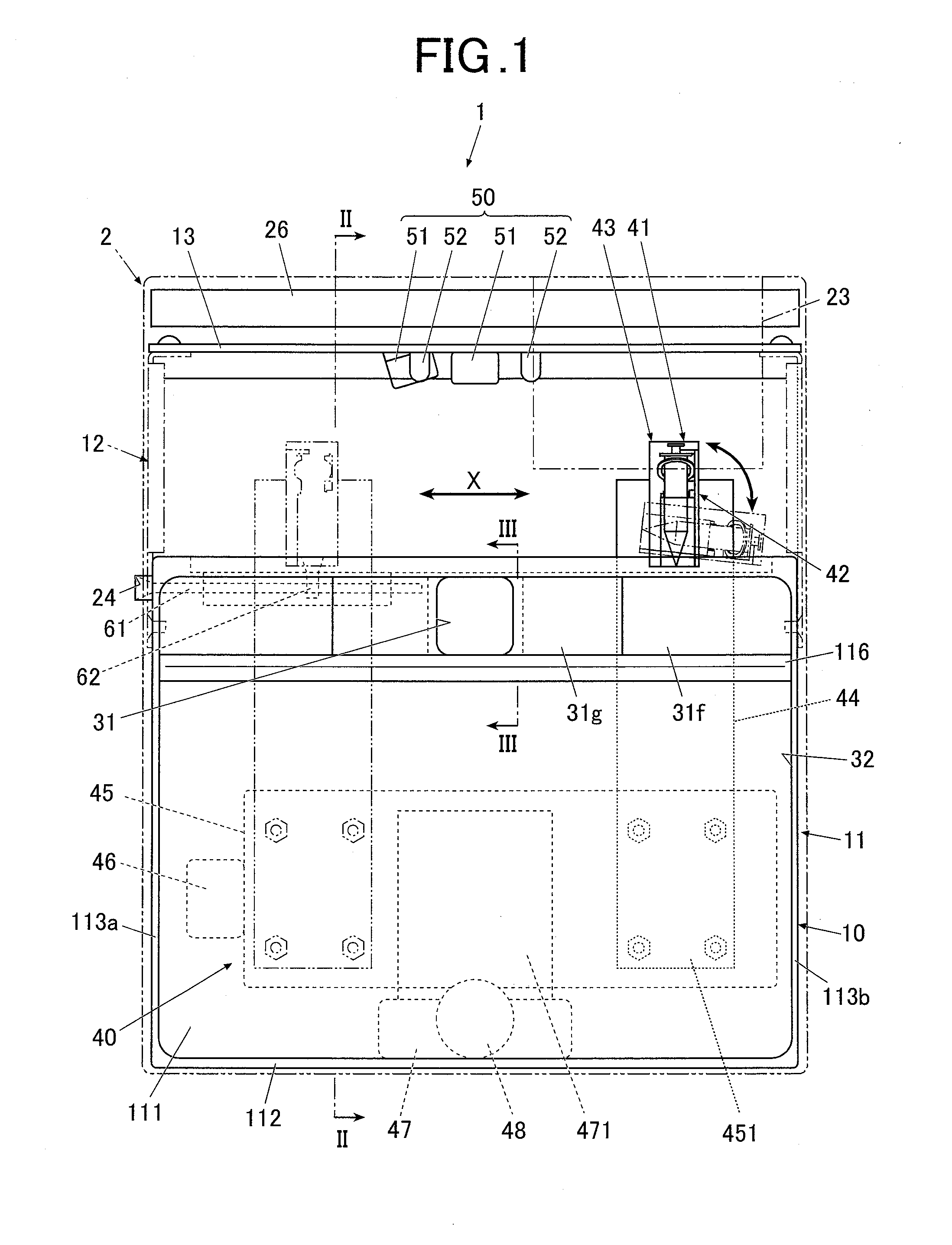
[0033]FIG. 1 is a front view of the drawing apparatus 1 in this embodiment.
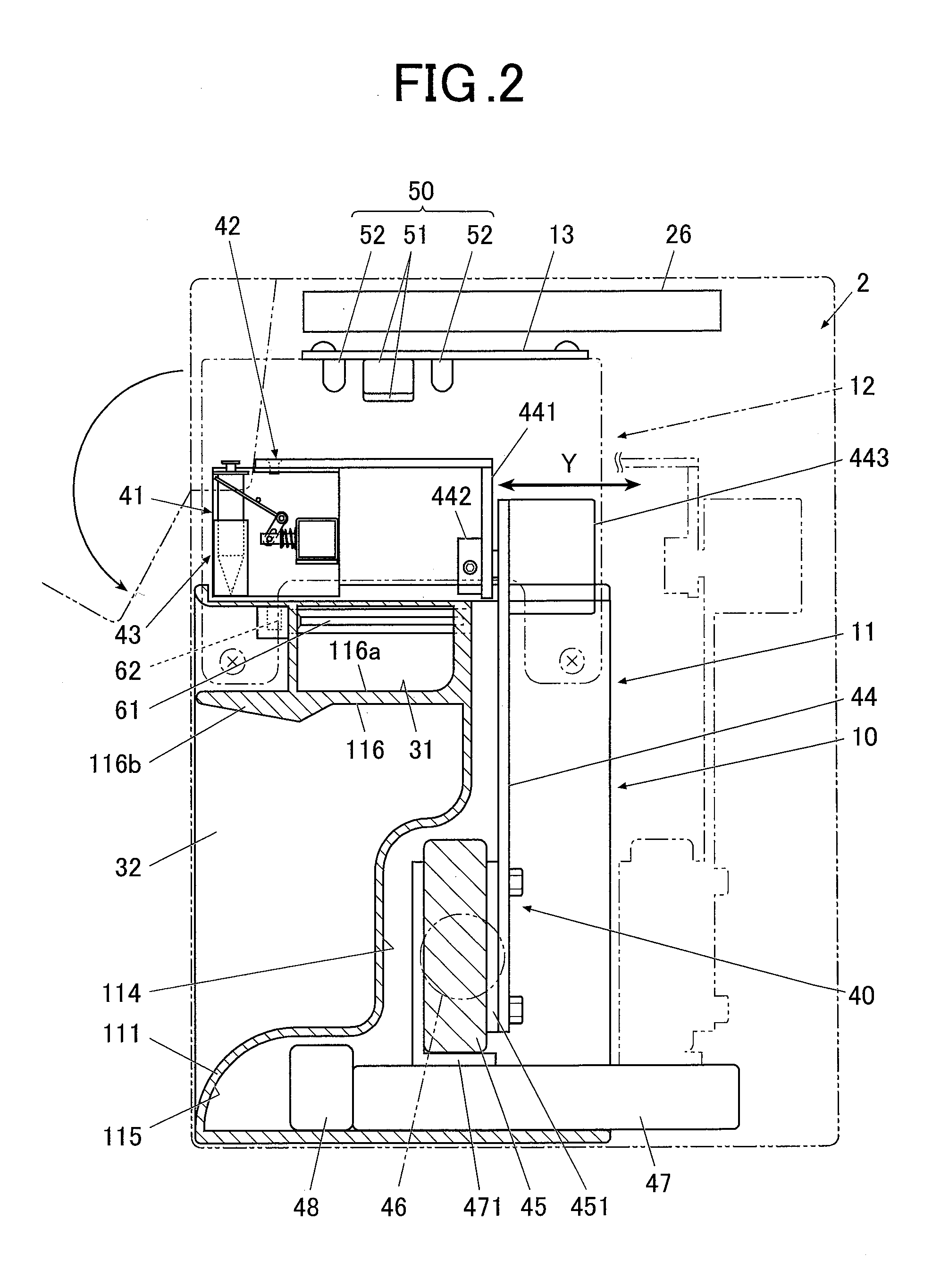
[0034]FIG. 2 is a sectional side view of the drawing apparatus 1 along the line II-II of FIG. 1.
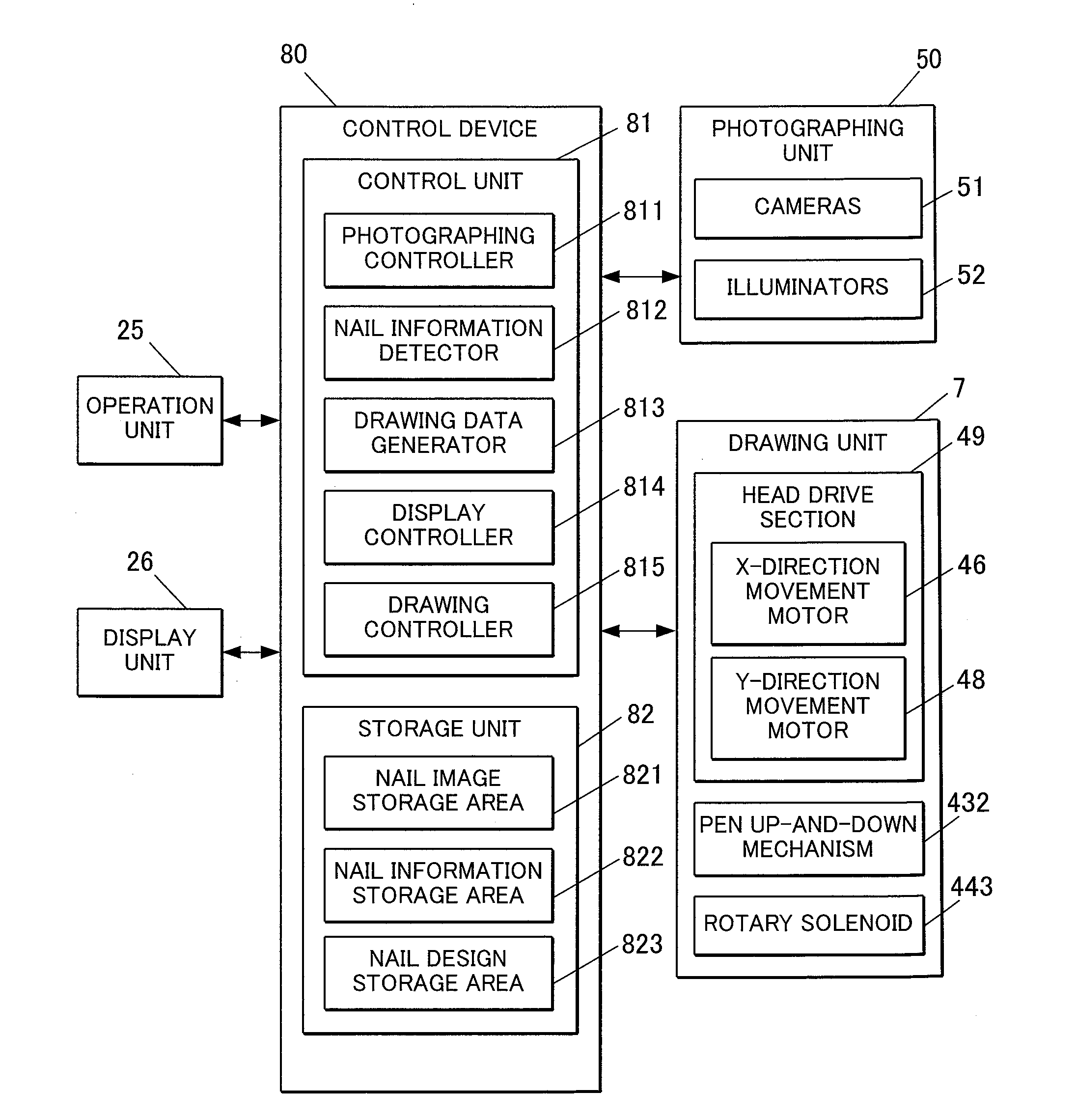
[0035]As shown in FIGS. 1 and 2, the drawing apparatus 1 is a nail printing apparatus to perform drawing on nails of fingers and includes a case body 2 and an apparatus body 10 contained in the case body 2.
[0036]In FIGS. 1 and 2, the case body 2 is indicated by two-dot chain lines.
[0037]A cover 23 for pen replacement is disposed at one end part of the upper front side of the case body 2. The cover 23 can be opened and closed so that a pen (drawing tool) 41 of a drawing unit 40, described later, can be replaced.
[0038]The cover 23 for pen replacement can turn about a hinge, for example, from a closing state to an opening state as shown in FIG. 2.
[0039]One lateral face (left face in FIG. 1 in...
second embodiment
[0277]A drawing apparatus of a second embodiment of the present invention will now be described with reference to FIGS. 6 to 9.
[0278]The second embodiment is different from the first embodiment only in the configuration of a drawing unit, and the features of the second embodiment different from those of the first embodiment will be described below in particular.
[0279]FIG. 6 is a front view of a drawing apparatus in the second embodiment.
[0280]FIG. 7 is a side view of the drawing apparatus in FIG. 6 with a part thereof shown in section to show the internal structure.
[0281]As shown in FIGS. 6 and 7, a drawing unit 7 includes a drawing head 70 having pens 71 for drawing, a head support member 441 to support the drawing head 70, a unit support member 44 to which the head support member 441 is connected through a shaft 442, a rotary solenoid 443 to rotate the drawing head 70 supported by the head support member 441 about the axis of the shaft 442, an X-direction movement stage 45 to move...
third embodiment
[0337]A drawing apparatus of a third embodiment of the present invention will now be described with reference to FIGS. 10 and 11.
[0338]The third embodiment is different from the first and second embodiments in the position of a rotary solenoid, and the features of the third embodiment different from those of the first and second embodiments will be described below in particular.
[0339]FIG. 10A is a top view of a drawing head 70.
[0340]FIG. 10B is a front view of the drawing head 70, seen from the direction of arrow b of FIG. 10A.
[0341]FIG. 10C is a side view of the drawing head 70, seen from the direction of arrow c of FIG. 10A.
[0342]As shown in FIGS. 10A to 10C, the drawing head 70 of the third embodiment includes a rotary carriage 72 that can hold a plurality of pens 71, similarly to the second embodiment.
[0343]In this embodiment, the drawing head 70 is supported by a head support member 445.
[0344]The unit support member 44 of this embodiment includes a projecting part 44a disposed ...
PUM
 Abstract
Description
Claims
Application Information