
Apparatus to Capture and Extract Drain Clog Debris

a technology of drain debris and apparatus, which is applied in water installations, lavatory sanitory, construction, etc., can solve the problems of simple drain clogs, general caustic, and clogged bathroom sinks, etc., and achieve the effect of convenient removal and insertion

Inactive Publication Date: 2015-06-25
LEI SKIP A
View PDF17 Cites 6 Cited by
  • Summary
  • Abstract
  • Description
  • Claims
  • Application Information

AI Technical Summary

Benefits of technology

The present invention is a device that can be used to clear blockages in drains. It is made from a flexible material that can bend and still keep its shape. The device has a part that can be inserted into the drain and turned to help clear the blockage. It is designed to be easily inserted and removed, and can be shaped differently for different drain sizes. The device also has micro barbs on the outside to help grab debris and free hair that may be causing the blockage, while the inside is smooth to allow the blockage to be drawn up into the device.

Problems solved by technology

Simple drain clogs have been a problem ever since the creation of plumbing.
Bathroom sinks, showers and tubs tend to be subject to clogs from hair and soap.
Whatever the substance, the substances tend over time to attach, ball up, and form clogs that slow, and eventually stop up the drain.
A drawback of chemicals is that they are generally caustic to the drain, and they can be deadly to the user as well as the environment.
And if not deadly, chemicals can get in the eyes of a user and potentially cause serious harm.
Large snake devices are expensive, and if not used correctly, can push the material causing a clog to move further down the drain.
First, the Luoma device has to be pushed into a clog, which may actually only push the clog deeper into the drain beyond the limited reach of the Luoma device.
Second, the Luoma device, having the barbed portions interspersed along its length, present sharp edges that pose a risk to the user who could be cut or poked by the barbed portions along the length of the device.

Method used


Image

  • Apparatus to Capture and Extract Drain Clog Debris
  • Apparatus to Capture and Extract Drain Clog Debris
  • Apparatus to Capture and Extract Drain Clog Debris

Examples


Embodiment Construction

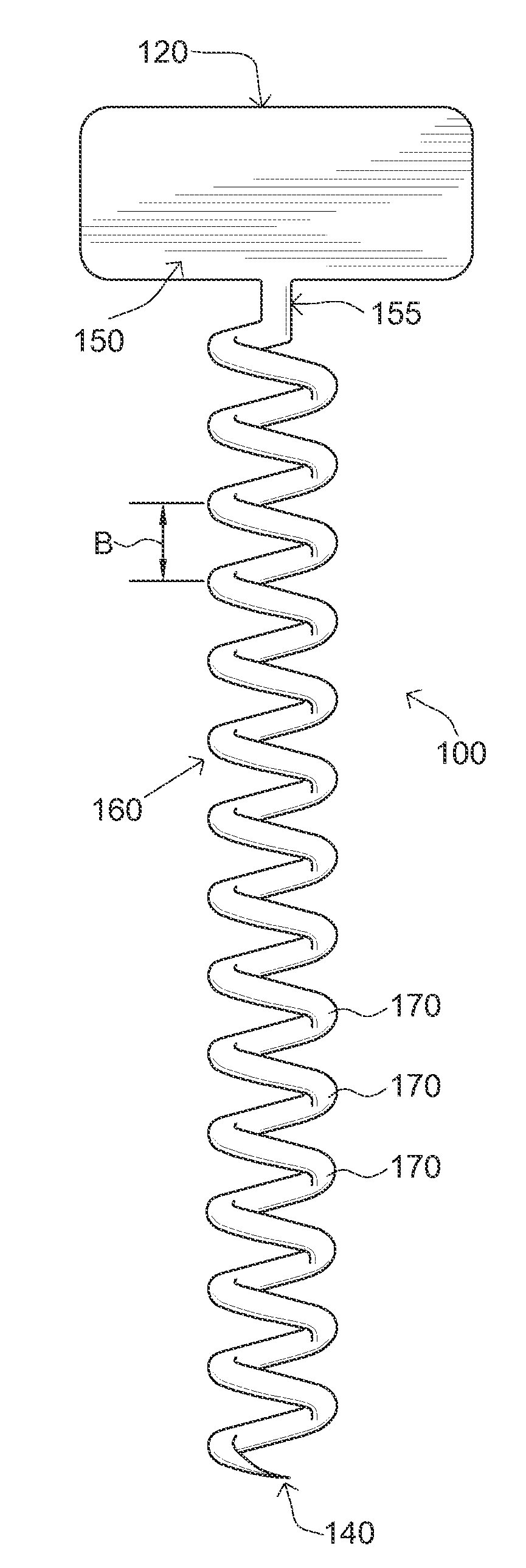
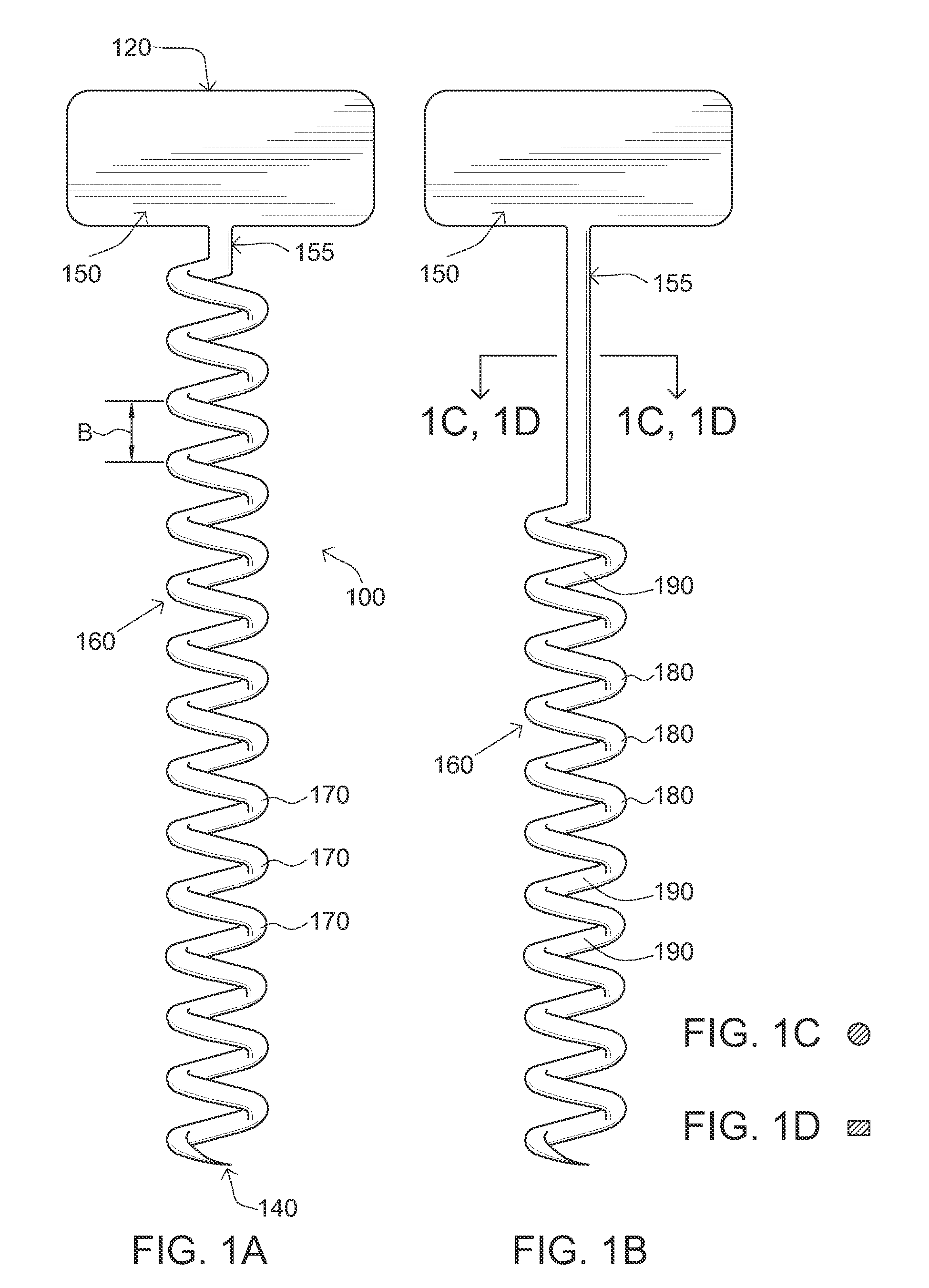
[0030]Referring now to the drawings, in particular FIG. 1A and FIG. 19, the apparatus of the present invention is generally shown in the Figures as reference numeral 100.

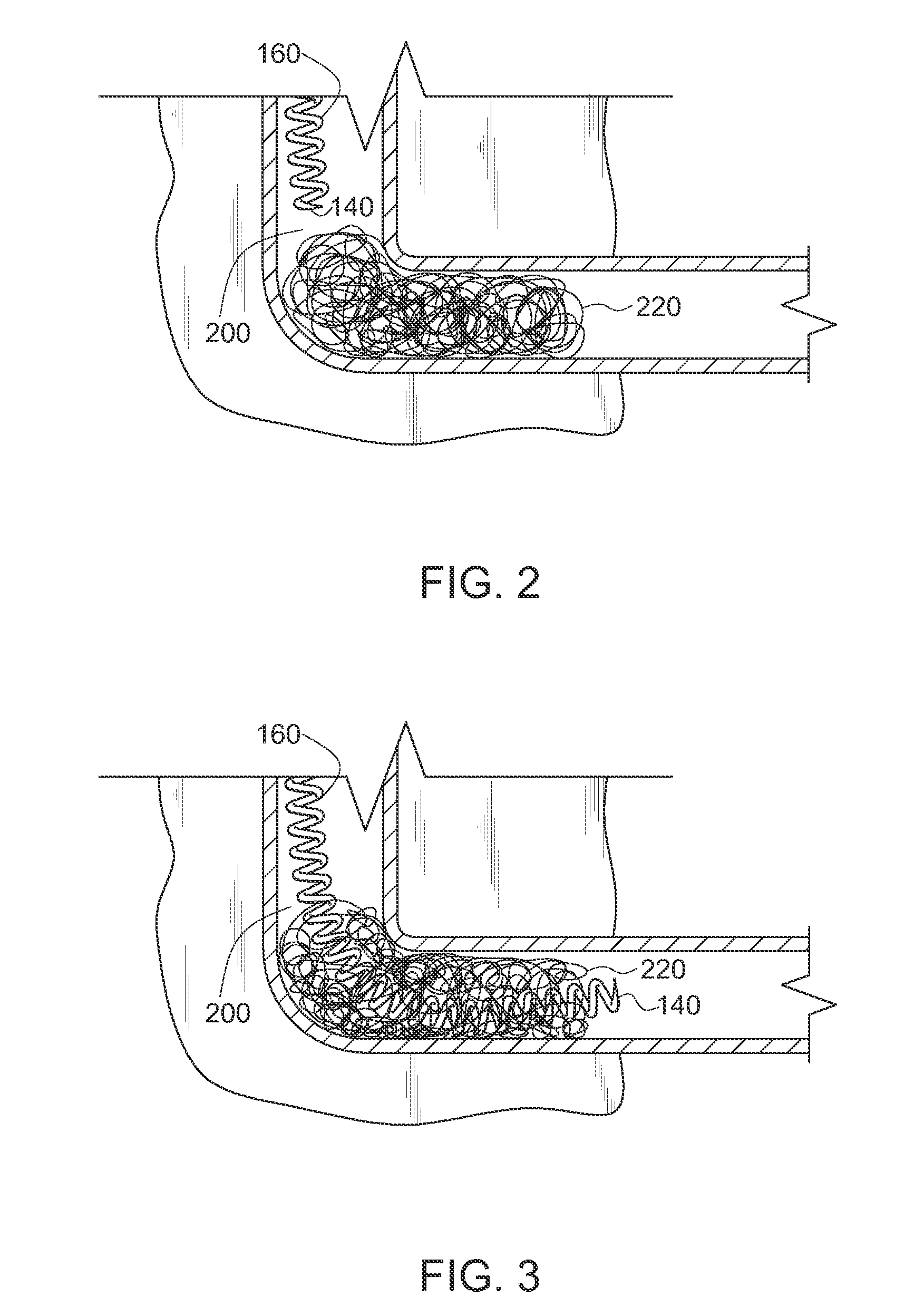
[0031]The apparatus 100 has a proximal end 120 and a distal end 140, and consists of a handle 150 with an extended or elongated shaft 155 formed into a coil 160. Preferably, the shaft and coil 160 is substantially of a cylindrical cross section as shown in FIG. 1C, where the shaft 155 is wound helically about an axis to form the coil 160 or “worm”, having a point at the lower, distal end 140 for initial insertion into a drain (as shown in FIGS. 2 and 3), although for safety reasons, the distal end 140 could be blunt. Alternatively, the coil 160 could be of a shaft 155 having a rectangular cross section as shown in FIG. 1D wound helically about an axis to form the coil 160.

[0032]The handle 150 at the upper, or proximal end 120, can be of any shape and size provided it can be gripped and turned (as shown in FIG. 5) to...


PUM


Abstract

An apparatus for removing a dog from a drain consists of an elongated, flexible shaft member with a corkscrew or coil member on one end and an integrated handle at the other end. Inserting the corkscrew end into a dogged drain and manually turning the handle allows the corkscrew portion of the apparatus to worm through the matter that is dogging the drain, and when the apparatus is pulled from the drain the dogging matter is held within the corkscrew member to capture the dogging matter or debris for easy removal.

Description

CROSS-REFERENCE TO RELATED APPLICATIONS[0001]Not ApplicableSTATEMENT REGARDING FEDERALLY SPONSORED RESEARCH OR DEVELOPMENT[0002]Not ApplicableREFERENCE TO SEQUENCE LISTING, A TABLE, OR A COMPUTER PROGRAM LISTING COMPACT DISC APPENDIX[0003]Not ApplicableBACKGROUND OF THE INVENTION[0004]This invention generally relates to a low cost, single use, disposable device for clearing a clog from a drain, and more particularly, for clearing a clog from a bathroom sink, shower, or bathtub drain.[0005]Simple drain clogs have been a problem ever since the creation of plumbing. Bathroom sinks, showers and tubs tend to be subject to clogs from hair and soap. Bathroom sinks in addition have toothpaste, shaving creams, hair jells as well as other substances that people use in the bathroom. Whatever the substance, the substances tend over time to attach, ball up, and form clogs that slow, and eventually stop up the drain.[0006]Consumers have had several paths to alleviate the problem of clogs by calli...

Claims


Application Information

Patent Timeline
Patent Type & Authority Applications(United States)
IPC IPC(8): E03C1/302
CPCE03C1/302E03C1/30
Inventor LEI, SKIP A.
Owner LEI SKIP A
Learn More