Optical connector

Inactive Publication Date: 2015-06-25
DELTA ELECTRONICS INC
View PDF5 Cites 1 Cited by
  • Summary
  • Abstract
  • Description
  • Claims
  • Application Information

AI Technical Summary

Benefits of technology

[0019]As mentioned above, the lens structure of the invention is directly coupled to the casing, so that the force of the plugging/unplugging fiber can be conducted from the lens structure to the casi

Problems solved by technology

Recently, the data processing speed and amount have been explosive increased, so the traditional cable may not afford and provide the desired bandwidth and transmission speed

Method used


Image

  • Optical connector
  • Optical connector
  • Optical connector

Examples


Embodiment Construction

[0023]The present invention will be apparent from the following detailed description, which proceeds with reference to the accompanying drawings, wherein the same references relate to the same elements.

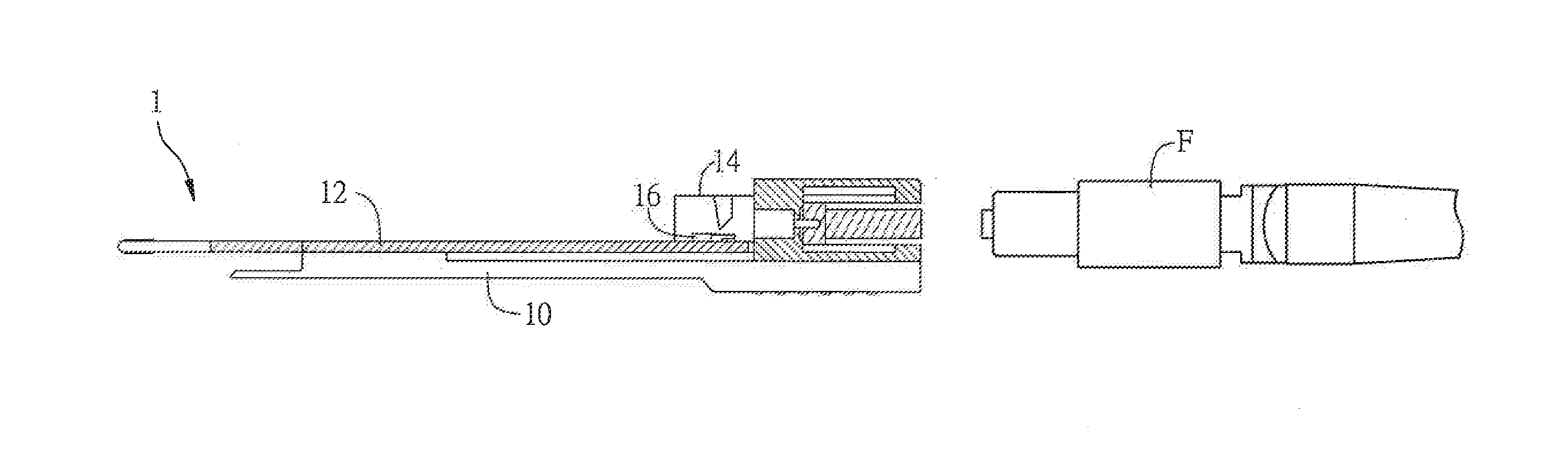
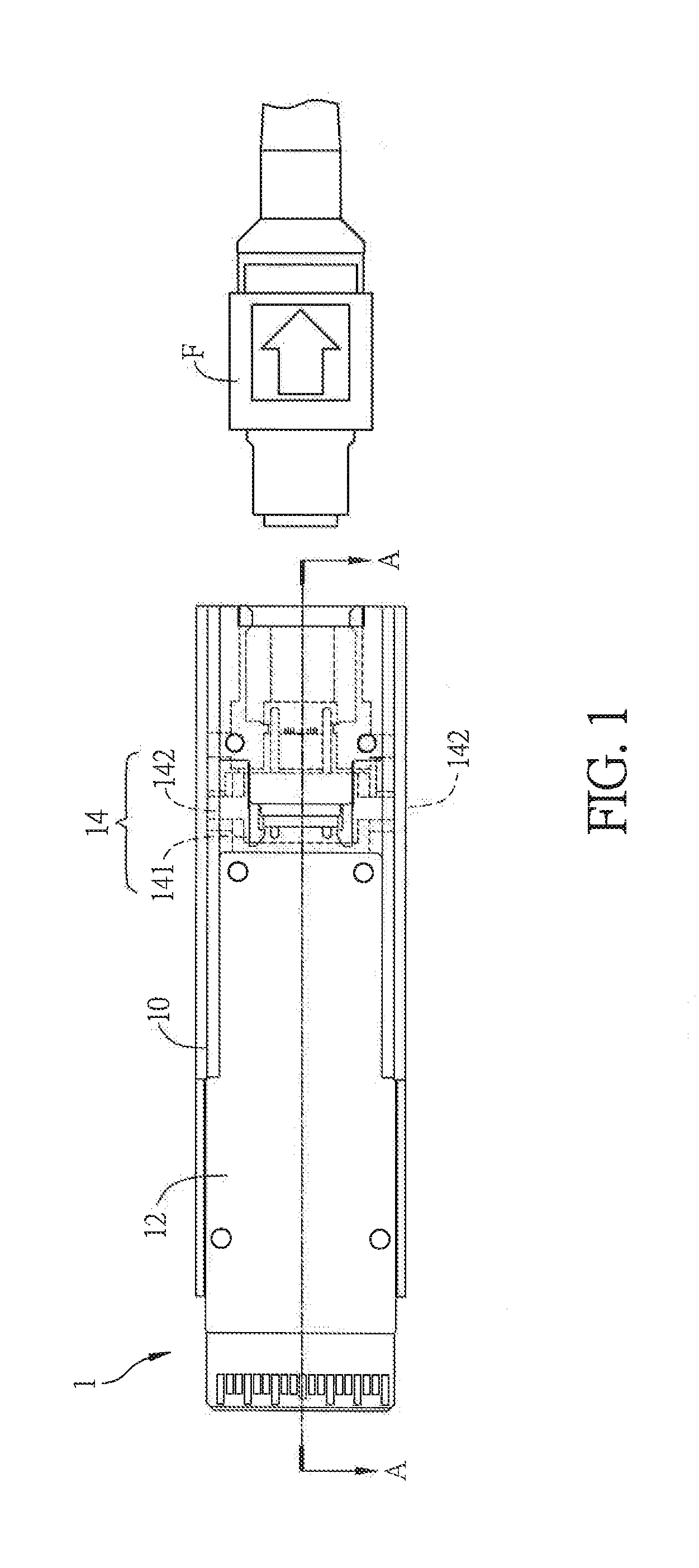
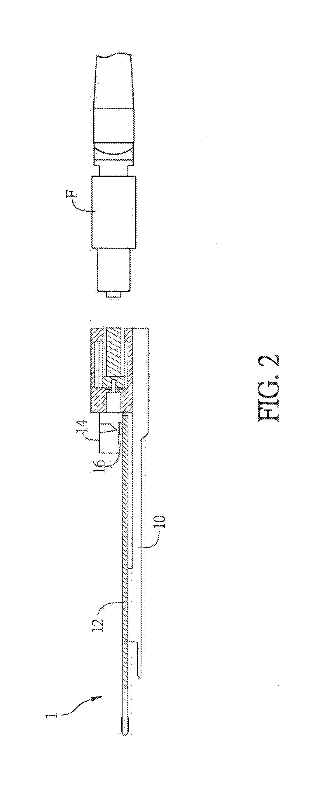
[0024]FIG. 1 is a schematic diagram showing an optical connector 1 according to an embodiment of the present invention, and FIG. 2 is a sectional view of the optical connector 1 along the line AA of FIG. 1.

[0025]Referring to FIGS. 1 and 2, the optical connector 1 includes a casing 10, a circuit structure 12, a lens structure 14 and an optical transceiver element 16.

[0026]For example, the casing 10 can be made of plastic, metal, stainless steel, alloy, ceramic, or any other material with sufficient rigidity. Besides, the casing 10 can be connected to other components by adhesion, wedging, embedding, fitting, clipping, filling or using at least one bolt, or they can be integrally formed as one piece.

[0027]The circuit structure 12 is disposed inside the casing 10 and is configured for tr...


PUM


Abstract

An optical connector is disclosed. The optical connector has a casing, a circuit structure, a lens structure and an optical transceiver element. The circuit structure is disposed inside the casing and configured for transmitting an electrical signal. The lens structure is directly fixed on the casing and coupled to a fiber adapter. The optical transceiver element is disposed on the circuit structure, and an optical signal is transmitted between the optical transceiver element and the fiber adapter through the lens structure.

Description

CROSS REFERENCE TO RELATED APPLICATIONS[0001]This Non-provisional application claims priority under 35 U.S.C. §119(a) on Patent Application No(s). 201310706459.9 filed in People's Republic of China on Dec. 20, 2013, the entire contents of which are hereby incorporated by reference.BACKGROUND OF THE INVENTION[0002]1. Field of Invention[0003]The present invention relates to an optical connector.[0004]2. Related Art[0005]Recently, the data processing speed and amount have been explosive increased, so the traditional cable may not afford and provide the desired bandwidth and transmission speed. Accordingly, the optical fiber is introduced to the data transmission and communication applications.[0006]The optical transmission through fibers has the advantages of no limitation in bandwidth, high speed transmission, longer transmission distance, and free from the electromagnetic interference. In general fiber communication, the optical signal travels through the fiber and reaches an optical...

Claims


Application Information

Patent Timeline
IPC IPC(8): G02B6/42
CPCG02B6/4206G02B6/428G02B6/4201G02B6/4204G02B6/4231G02B6/4246G02B6/4292
Inventor LIAO, YU-HSIENYOU, HONG-BINYIU, GOW-ZIN
Owner DELTA ELECTRONICS INC
Why Eureka
Try Eureka